
Die-casting forming device for aluminum product

A technology of die-casting and aluminum products, which is applied in the field of aluminum product processing, can solve the problems of inconvenient material removal, etc., and achieve the effect of improving convenience and preventing deviation

Inactive Publication Date: 2020-03-06
任彦成
View PDF8 Cites 0 Cited by
  • Summary
  • Abstract
  • Description
  • Claims
  • Application Information

AI Technical Summary

Problems solved by technology

An aluminum ingot die-casting device in the above-mentioned patent has the following disadvantages: when the aluminum product is die-casted, the aluminum product after die-casting needs to be stripped, but the aluminum product is embedded in the mold cavity due to pressure during die-casting. Therefore, it is not convenient for stripping

Method used


Image

  • Die-casting forming device for aluminum product
  • Die-casting forming device for aluminum product
  • Die-casting forming device for aluminum product

Examples


Embodiment 1

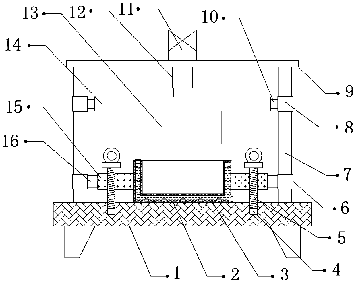
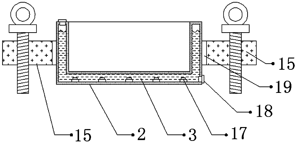
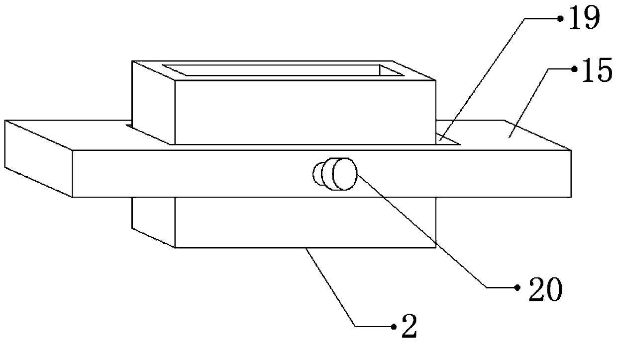
[0029] Reference Figure 1-3 , A die-casting molding device for aluminum products, comprising a fixing base 1. Both sides of the outer wall of the top of the fixing base 1 are connected with fixing columns 7 by bolts, and the outer walls of the two fixing columns 7 are slidably connected with a first sliding sleeve 6, two The outer walls on the opposite side of the first sliding sleeve 6 are all rotatably connected with a rotating shaft 16 through a bearing, and the outer walls on the opposite side of the two rotating shafts 16 are both connected with a fixing plate 15 by bolts, and the top outer wall of the fixing plate 15 is fixed. There is a template 2 inside the fixed port 19, the top outer wall of the template 2 is provided with a mold groove, the top outer walls of the two fixed columns 7 are connected with a support plate 9 by bolts, and the bottom outer wall of the support plate 9 is connected by bolts There is a cylinder 12, the bottom outer wall of the cylinder 12 is c...

Embodiment 2

[0039] Reference Figure 4-5 , A die-casting molding device for aluminum products. Compared with Embodiment 1, this embodiment has a plurality of limiting grooves 22 on the outer wall of the top of the fixing seat 1, and the inner wall of the bottom of the limiting groove 22 is bonded with a cushion 23, a template The bottom outer wall of 2 is provided with a plurality of protrusions 21, and the protrusions 21 are matched with the limiting groove 22.

[0040] Working principle: When in use, the liquid is injected into the mold groove. After the injection is completed, the air pump 11 is started to make the cylinder 12 drive the pressure head 13 downward, so that the pressure head 13 performs die-casting treatment on the liquid, and passes through the second sliding sleeve 8. And the fixed column 7 can guide the downward movement of the indenter 13 to prevent the displacement of the indenter 13 due to shaking during the movement and affect the die casting of aluminum products. Dur...


PUM


Abstract

The invention discloses a die-casting forming device for an aluminum product. The die-casting forming device comprises a fixed seat. Fixed columns are fixed to two sides of the outer wall of the top of the fixed seat, first sliding sleeves are slidably connected to the outer walls of the two fixed columns, the outer walls of opposite sides of the two first sliding sleeves are rotatably connected to rotating shafts through bearings, fixed plates are fixed to the outer walls of opposite sides of the two rotating shafts, fixed openings are formed in the outer walls of the tops of the fixed plates, die plates are arranged in the fixed openings, die cavities are formed in the outer walls of the tops of the die plates, supporting plates are fixed to the outer walls of the tops of the fixed plates, and air cylinders are fixed to the outer walls of the bottoms of the supporting plates. The die-casting forming device can avoid a condition that stripping of the aluminum product is affected as the aluminum product is embedded into the die cavities as a result of pressure during die casting, the die plates can be detached conveniently and different die plates are replaced conveniently, and a condition of deviation of die casting of the aluminum product as the die plates deviate as a result of vibration during die casting can be prevented.

Description

Technical field [0001] The invention relates to the technical field of aluminum product processing, in particular to a die-casting molding device for aluminum products. Background technique [0002] Aluminum products are the general term for daily necessities and industrial products processed with aluminum alloy as the main raw material. Aluminum alloy is the general term for aluminum-based alloys. When aluminum products are processed, the aluminum products need to be formed by a die-casting device. . [0003] After searching, the Chinese patent grant number CN208357762U discloses an aluminum ingot die-casting device, including a support base, a lower mold is provided on the top of the bottom plate, a first chute is provided on the top of the lower mold, and the lower mold passes through the first The chute is slidably connected to the upper mold, the surface of the upper mold is provided with a sealing cover, the middle of the top of the upper mold is provided with a connecting b...

Claims


Application Information

Patent Timeline
Patent Type & Authority Applications(China)
IPC IPC(8): B22D17/00B22D17/20B22D17/22B22D17/24
CPCB22D17/00B22D17/2015B22D17/2236B22D17/24
Inventor 任彦成
Owner 任彦成
Learn More