Transfer working table capable of freely changing materials

A processing table, free technology, applied in the direction of transportation and packaging, conveyor objects, etc., can solve the problems of production efficiency decline, unfavorable refueling production, increase equipment footprint, etc., to reduce manpower consumption and improve intelligence degree, the effect of reducing the cost of erection

Inactive Publication Date: 2020-03-06
张景仁
View PDF6 Cites 6 Cited by
  • Summary
  • Abstract
  • Description
  • Claims
  • Application Information

AI Technical Summary

Problems solved by technology

[0003] In the process of circuit board mounting, the electrical components are usually installed on the circuit board by a placement machine. Due to the different electrical components on the circuit board, the types of electrical components on different circuit boards are different, and the order of loading places is also different. Therefore, one type of circuit board can only be used for one placement machine, and different circuit board placement needs to be assembled by setting up different production lines, which not only increases the cost, but also increases the footprint of the equipment, which is not conducive to timely Refueling production, and repeated disassembly of the material frame of the placement machine, resulting in a decline in production efficiency and reducing the service life of the placement machine. The existing transfer table is less intelligent and can only transfer materials in one direction , it is impossible to identify and classify the materials, resulting in the transfer platform can only realize the temporary transfer of materials, and cannot realize the precise control of the transfer direction
[0004] For this purpose, a transfer processing table with free refill is provided to solve the problem of fast refueling production of different circuit boards

Method used


Image

  • Transfer working table capable of freely changing materials
  • Transfer working table capable of freely changing materials
  • Transfer working table capable of freely changing materials

Examples


Embodiment Construction

[0026] The following will clearly and completely describe the technical solutions in the embodiments of the present invention with reference to the accompanying drawings in the embodiments of the present invention. Obviously, the described embodiments are only some, not all, embodiments of the present invention. Based on the embodiments of the present invention, all other embodiments obtained by persons of ordinary skill in the art without making creative efforts belong to the protection scope of the present invention.

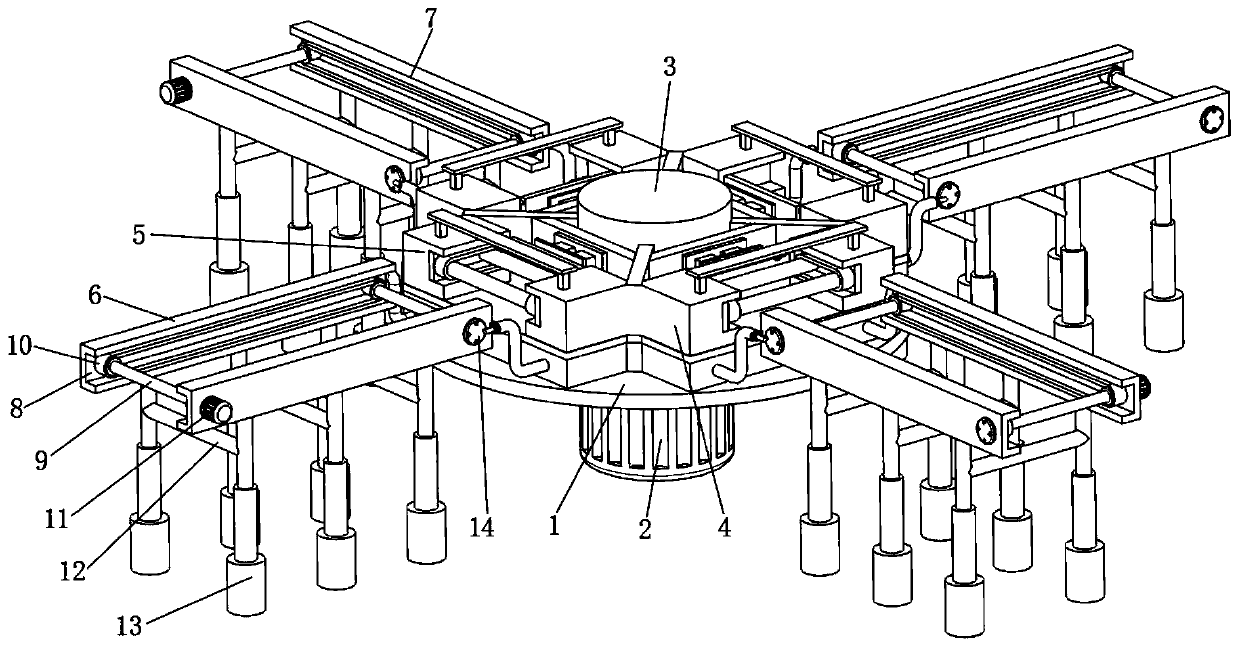
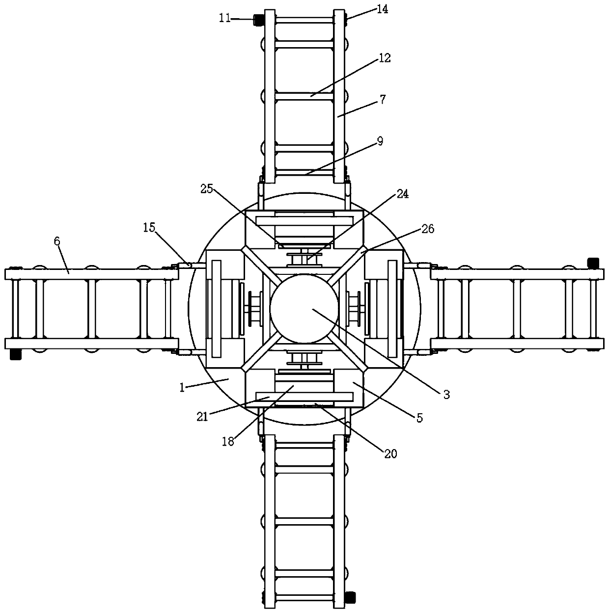
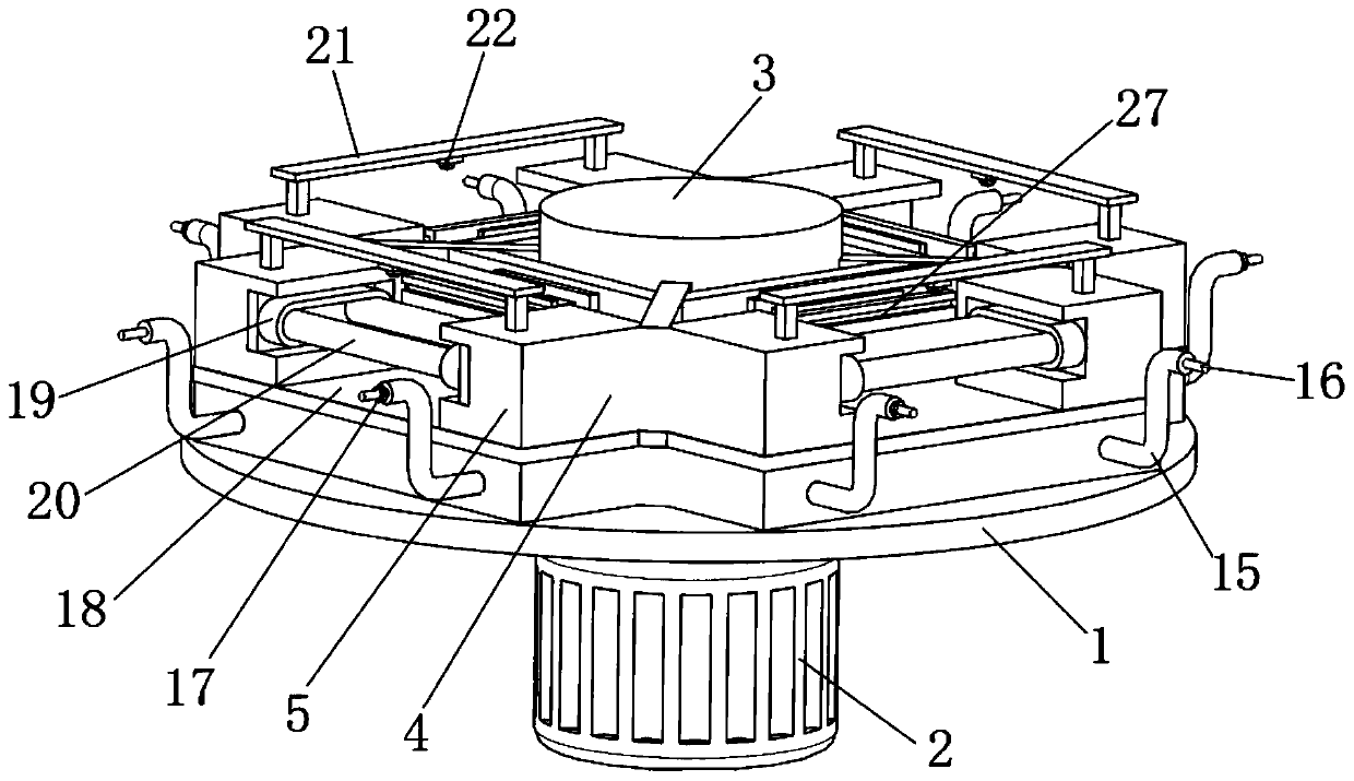
[0027] see Figure 1 to Figure 5 , the present invention provides a technical solution:

[0028] A processing table for transfer that can be freely changed, including a transfer table 1, a servo motor 2 is installed at the lower end of the transfer table 1, a main shaft 3 is installed on the upper end of the servo motor 2, and the outer wall of the lower end of the main shaft 3 runs through the transfer table. The workbench 1 and the outer wall of the upper e...


PUM


Abstract

The invention relates to the technical field of transfer working tables, in particular to a transfer working table capable of freely changing materials. The transfer working table capable of freely changing materials comprises a transfer workbench, a servo motor is arranged at the lower end of the transfer workbench, the left side of the transfer workbench is provided with a feeding support, the other three directions of the transfer workbench are provided with material changing supports, and the upper end of the servo motor is rotatably provided with a main rotating shaft. The transfer working table has the beneficial effects that a plurality of chip mounters are matched with one feeding support to be simultaneously used by arranging the transfer working table, the space resource occupiedby the machine is saved, the production line erection cost is reduced, and the production efficiency is improved; and due to the fact that the support with identification equipment is arranged and matched with the rotation angle of the servo motor, different circuit boards are conveyed to the portions, corresponding to the chip mounters, of the feeding support, the purpose of producing the multiple circuit boards on one production line is realized, and material changing is convenient.

Description

technical field [0001] The invention relates to the technical field of transfer processing tables, in particular to a transfer processing table that can freely change materials. Background technique [0002] With the development of flexible circuit boards, more and more electronic devices use circuit flexible boards for circuit assembly, which makes the operating performance of circuit boards more stable. [0003] In the process of circuit board mounting, the electrical components are usually installed on the circuit board by a placement machine. Due to the different electrical components on the circuit board, the types of electrical components on different circuit boards are different, and the order of loading places is also different. Therefore, one type of circuit board can only be used for one placement machine, and different circuit board placement needs to be assembled by setting up different production lines, which not only increases the cost, but also increases the f...

Claims


Application Information

Patent Timeline
Patent Type & Authority Applications(China)
IPC IPC(8): B65G47/64
CPCB65G47/64
Inventor 张景仁
Owner 张景仁
Why Eureka
Try Eureka