Lightning trip-out rate test method considering line soil resistivity differentiation
What is AI technical title?
AI technical title is built by Patsnap AI team. It summarizes the technical point description of the patent document.
A technology of soil resistivity and lightning tripping rate, which is applied in the direction of calculation, measurement of electricity, calculation model, etc., can solve problems such as difficult research work
Active Publication Date: 2020-03-06
GUANGDONG POWER GRID CO LTD +1
View PDF16 Cites 10 Cited by
Summary
Abstract
Description
Claims
Application Information
AI Technical Summary
This helps you quickly interpret patents by identifying the three key elements:
Problems solved by technology
Method used
Benefits of technology
Problems solved by technology
For the influence of different soil resistivity on the lightning withstand level of the whole system, the research work on the lightning tripping rate of transmission lines is difficult. At present, solving the shielding tripping fault of transmission lines is still a world-class problem
Method used
Image
Click on the blue label to locate the original text in one second.
Reading with bidirectional positioning of images and text.
Examples
Embodiment 1
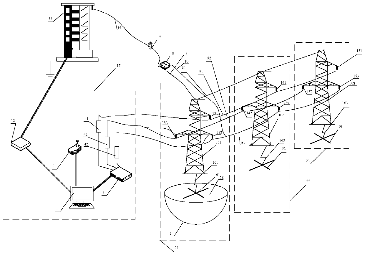
[0074] Taking into account the lightning tripping rate test method of the line soil resistivity difference, the test platform is first built, such as figure 1 As shown, the platform includes an impulse voltage generator 11, a data measurement analysis control module 17, a wireless current sensor 7, a coaxial cable 1 24, a coaxial cable 2 9, a coaxial cable 3 10, a bidirectional contact 8, a first base Tower 21, second base tower 22, third base tower 23, lightning protection line 81, A-phase line 91, B-phase line 92, C-phase line 93;
[0075] The output end of the impulse voltage generator 11 is connected to the bidirectional contact 8 through the coaxial cable one 24, and the bidirectional contact output ends are respectively connected to the coaxial cable two 9 and the coaxial cable three 10, wherein the coaxial cable two 9 is connected to On the top of the first base tower 21, the coaxial cable 3 10 is connected to the C-phase line 93 of the first base tower 21, and the wire...
Embodiment 2
[0082] A test method for lightning tripping rate taking into account the difference in line soil resistivity, comprising the following steps:
[0083] S1: Simulate a lightning strike on the top of a transmission line tower, and conduct a counter-attack lightning resistance level test;
[0084] S2: For the high soil resistivity area, change the soil resistivity of the soil 18 in the sand tank 5, starting from 550Ω·m, take a soil resistivity at an interval of 50Ω·m, and repeat step S1 to measure different soil resistivities The lower counter-attack lightning resistance level;
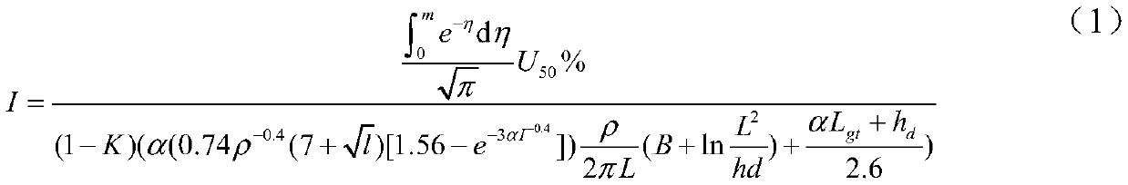
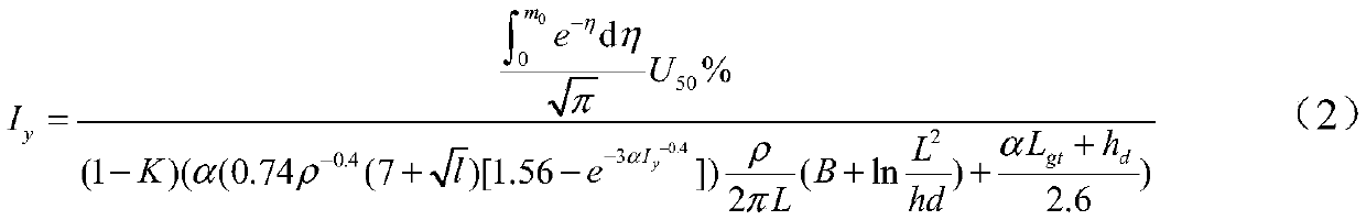
[0085] S3: Calculate the theoretical value I of counter-attack lightning resistance level under different soil resistivity by the following formula:
[0086]
[0087] In the formula, L is the total length of the grounding device conductor, h is the buried depth of the grounding device, d is the diameter of the grounding device conductor, B is the shape factor, l is the geometric dimension, L gt is th...
PUM
Abstract
The invention provides a lightning trip-out rate test method considering line soil resistivity differentiation. The method is characterized in that a test platform is built, and the test platform comprises an impulse voltage generator, a data measurement analysis control module, a wirelesscurrent sensor, a coaxial cable I, a coaxial cable II, a coaxial cable III, a first base tower, a second basetower, a third base tower, a lightning conductor, an A-phase line, a B-phase line and a C-phase line. The test method comprises the steps that the coaxial cable I is connected with the impulse voltage generator and a bidirectional contact; the other end of the bidirectional contact is connected with the C-phase line and the tops of the towers; a generator connecting line is surrounded by the wirelesscurrent sensor; measurement data are fed back to the data measurement analysis control module through the wirelesscurrent sensor; and the lightning trip-out rate is obtained through calculation.According to the invention, the lightning trip-out rate of a power transmission line under different soil resistivity conditions can be effectively calculated, so that lightning safety evaluation ofthe power transmission line and the tower structure can be realized.
Description
technical field [0001] The invention belongs to the field of lightning resistance performance analysis of electric power systems, in particular to a lightning striketripping rate test method taking into account the difference of line soil resistivity. Background technique [0002] Lightningstroketransmission line faults are the main problem affecting the safe transportation of power systems. Transmission and distribution network tripping accidents caused by lightning strikes occur frequently. Lightning trip accidents of lines account for more than 60% of transmission line accidents. For the impact of different soil resistivity on the lightning withstand level of the entire system, the research work on the lightning tripping rate of transmission lines is difficult. At present, solving the shielding tripping fault of transmission lines is still a world-class problem. [0003] In order to determine from which aspect the transmission line and tower should be transformed, red...
Claims
Application Information
Patent Timeline
Application Date:The date an application was filed.
Publication Date:The date a patent or application was officially published.
First Publication Date:The earliest publication date of a patent with the same application number.
Issue Date:Publication date of the patent grant document.
PCT Entry Date:The Entry date of PCT National Phase.
Estimated Expiry Date:The statutory expiry date of a patent right according to the Patent Law, and it is the longest term of protection that the patent right can achieve without the termination of the patent right due to other reasons(Term extension factor has been taken into account ).
Invalid Date:Actual expiry date is based on effective date or publication date of legal transaction data of invalid patent.

