Automatic arraying control device of log-periodic antenna array and arraying method thereof

A technology of log-periodic antenna and control device, which is applied to log-periodic antennas, antenna arrays, antenna supports/installation devices, etc., can solve the problems of difficult adjustment of log-periodic antenna arrays and high risks of high-altitude operations.

Active Publication Date: 2020-03-06
SHENZHEN WAVE TELECOMM TECH CO LTD
View PDF18 Cites 4 Cited by
  • Summary
  • Abstract
  • Description
  • Claims
  • Application Information

AI Technical Summary

Problems solved by technology

[0004] Based on this, it is necessary to address the above problems and provide an automatic array control device for logarithmic periodic antenna arrays, which can automat

Method used


Image

  • Automatic arraying control device of log-periodic antenna array and arraying method thereof
  • Automatic arraying control device of log-periodic antenna array and arraying method thereof
  • Automatic arraying control device of log-periodic antenna array and arraying method thereof

Examples


Embodiment 1

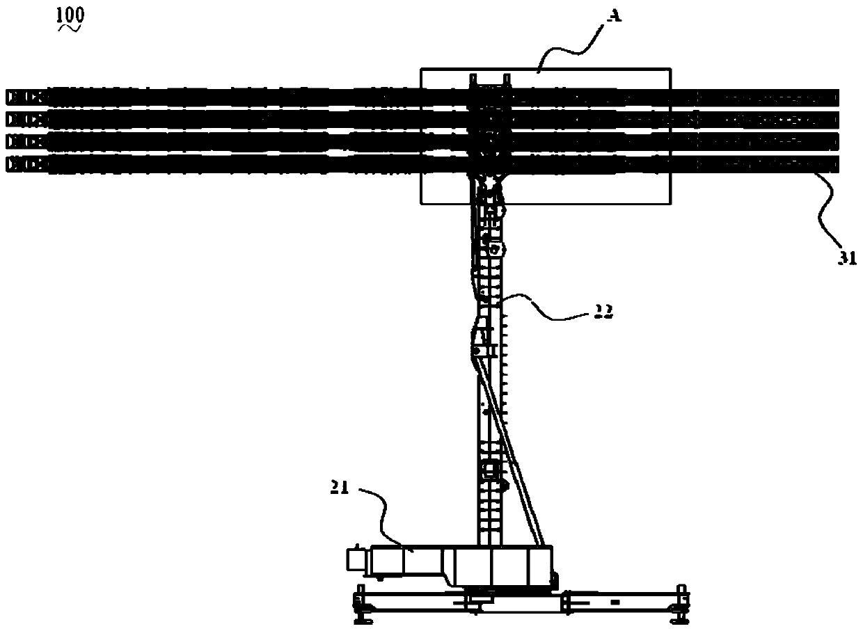
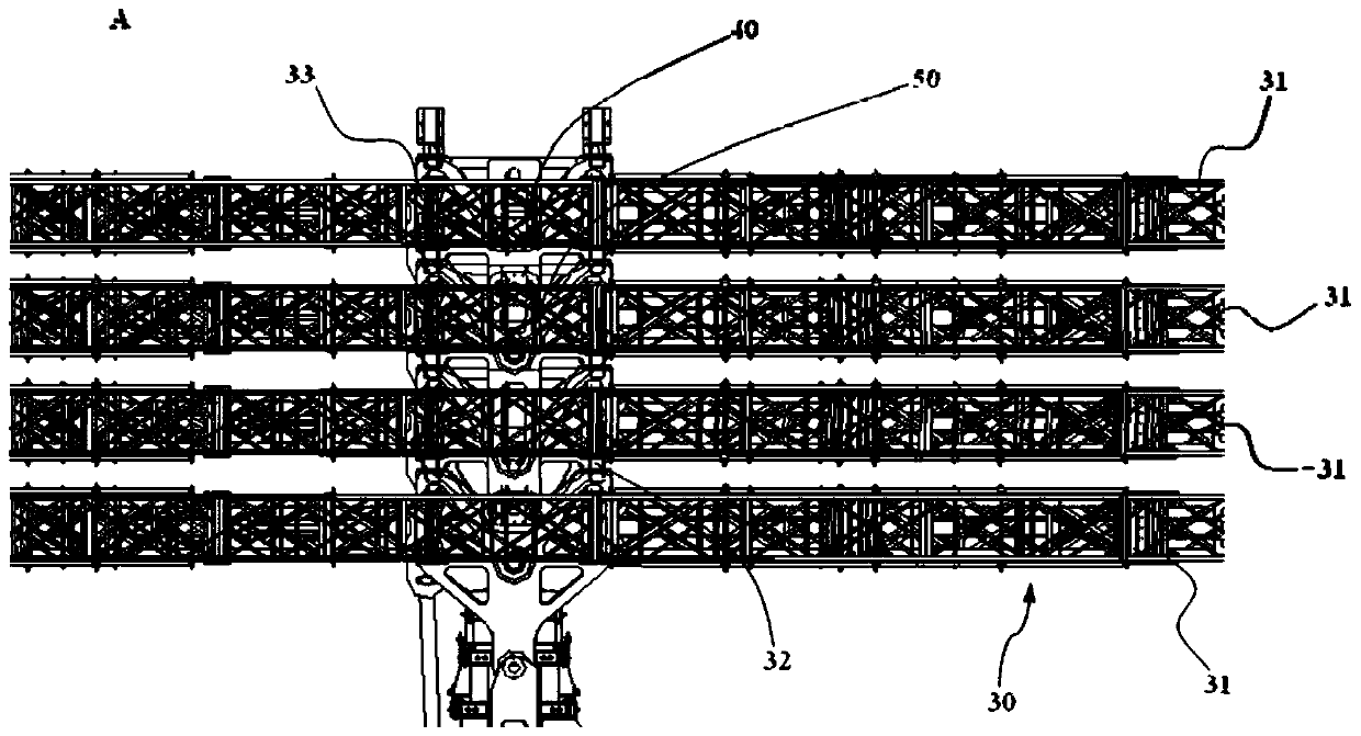
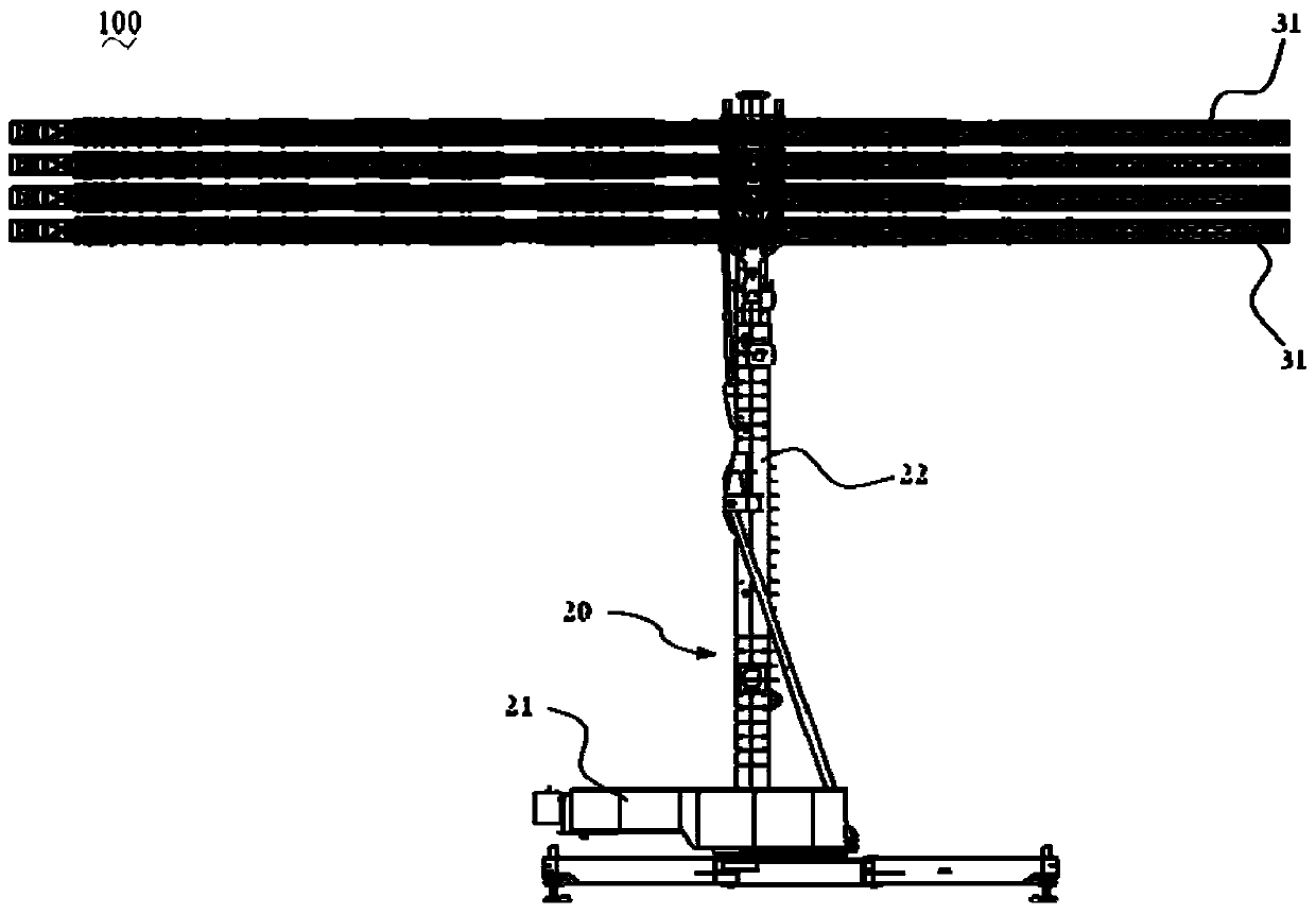
[0070] The log-periodic antenna array of this embodiment includes a first-layer antenna and a second-layer antenna. The first-layer antenna has a first connecting portion, and the first connecting portion has a first pin; the second antenna has a second connecting portion, and the second The connecting part has a second pin.

[0071] There are at least two bolt driving mechanisms, wherein the two bolt driving mechanisms are respectively connected to the first bolt and the second bolt.

[0072] The number of pin hole detection mechanisms is at least two, and the two pin hole detection mechanisms are installed on the first connection part and the second connection part.

[0073] The number of antenna retractable mechanisms is at least two, and the two antenna retractable mechanisms are respectively installed on the first-layer antenna and the second-layer antenna.

[0074] The lifting arm includes a first arm shaft and a second arm shaft connected to the first arm shaft, the fi...

Embodiment 2

[0085] The log-periodic antenna array of this embodiment includes a first-layer antenna, a second-layer antenna and a third-layer antenna. The first-layer antenna has a first connecting portion, and the first connecting portion has a first pin; the second antenna has a second The connecting part, the second connecting part has a second pin; the third-layer antenna has a third connecting part, and the third connecting part has a third pin.

[0086] The number of bolt driving mechanisms is at least three, and the three bolt driving mechanisms are respectively connected to the first bolt, the second bolt, and the third bolt.

[0087] The number of pinhole detection mechanisms is at least three, and the three pinhole detection mechanisms are installed on the first connection part, the second connection part and the third connection part.

[0088] The number of the antenna retractable mechanisms is at least three, and the three antenna retractable mechanisms are installed on the fi...


PUM


Abstract

The invention relates to an automatic arraying control device of a log-periodic antenna array and an arraying method thereof. The automatic arraying control device comprises an antenna lifting mechanism, the log-periodic antenna array, a plurality of plug pin driving mechanisms, a plurality of pin hole detection mechanisms, a plurality of antenna folding and unfolding mechanisms and a control module. The lifting mechanism comprises a supporting table and a lifting arm. The lifting arm comprises a plurality of arm shafts, every two adjacent arm shafts are movably connected and pin holes are formed in the arm shafts. The log-periodic antenna array comprises a plurality of layers of antennas, each layer of antenna is provided with a connecting part, the connecting part of each layer of antenna is provided with a plug pin and each layer of antenna is movably connected with one arm shaft. Each plug pin driving mechanism is arranged on one connecting part and is connected with the plug pin.The pin hole detection mechanisms are installed at the position close to the plug pins of the connecting parts. Each antenna folding and unfolding mechanism is installed on one layer of antenna. The control module is electrically connected with the pin hole detection mechanisms, the plug pin driving mechanisms, the antenna lifting mechanism and the antenna folding and unfolding mechanisms. Automatic and accurate array forming can be realized and safety and reliability can be achieved.

Description

technical field [0001] The invention relates to the technical field of communication equipment, in particular to an automatic formation control device and formation method of a logarithmic periodic antenna array. Background technique [0002] The short-wave antenna refers to the transmitting or receiving antenna working in the short-wave band (3-30MHz). Shortwave mainly uses ionospheric reflection propagation for communication, so it is not restricted by network hubs and relay conditions, and is one of the important means of modern long-distance radio communication. Antenna bandwidth and antenna gain are important indicators of the antenna, and they are also key indicators that restrict the communication distance of the antenna. [0003] In order to meet the requirement that the antenna has both large bandwidth and high gain, multiple pairs of log-periodic antennas are often combined in a certain way, then there will be a coupling relationship between the antennas, so the a...

Claims


Application Information

Patent Timeline
IPC IPC(8): H01Q1/12H01Q1/36H01Q11/10H01Q21/00
CPCH01Q1/12H01Q1/36H01Q11/10H01Q21/00
Inventor 张少林陈诗桓
Owner SHENZHEN WAVE TELECOMM TECH CO LTD
Why Eureka
Try Eureka