
Ultrasonic Probes and Ultrasonic Treatment Components

An ultrasonic, treatment part technology, used in medical science, surgery, endoscopic cutting instruments, etc., can solve problems such as slippage and difficulty in starting to form holes.

Active Publication Date: 2022-08-02
OLYMPUS CORP
View PDF6 Cites 0 Cited by
  • Summary
  • Abstract
  • Description
  • Claims
  • Application Information

AI Technical Summary

Problems solved by technology

The tip surface of the ultrasonic probe tends to slip relative to the treatment object, and it is sometimes difficult to start forming holes

Method used


Image

  • Ultrasonic Probes and Ultrasonic Treatment Components
  • Ultrasonic Probes and Ultrasonic Treatment Components
  • Ultrasonic Probes and Ultrasonic Treatment Components

Examples


no. 1 Embodiment approach

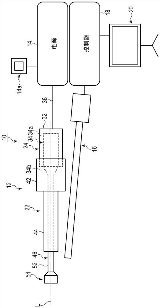
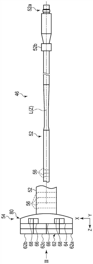
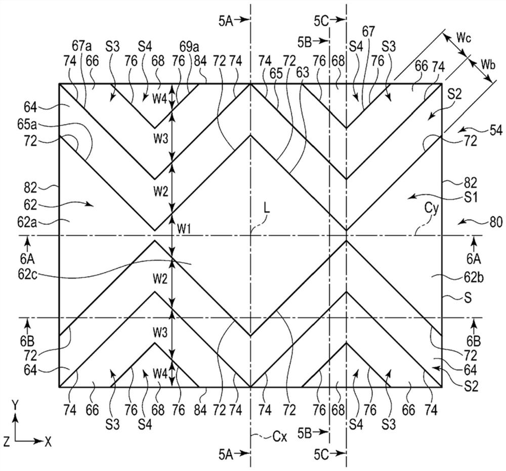
[0055] use Figure 1 to Figure 9E The first embodiment will be described.

[0056] like figure 1 As shown, the treatment system 10 of this embodiment includes an ultrasonic treatment unit 12 , a power source (first controller) 14 , an arthroscope (endoscope) 16 , a controller (second controller) 18 , and a display 20 . The treatment system 10 is preferably used with a perfusion device, not shown. Therefore, when the treatment using the treatment system 10 is performed, the perfusion fluid can be circulated while filling the joint cavity 110a of the knee joint 110, for example. Furthermore, the ultrasonic treatment assembly 12 and the arthroscope 16 of the treatment system 10 can be used for treatment within the perfusate-filled joint cavity 110a.

[0057] The arthroscope 16 is used to observe, for example, the inside of the knee joint 110 of the patient, that is, the inside of the joint cavity 110a. The controller 18 takes in the image obtained by the arthroscope 16 and p...

no. 2 Embodiment approach

[0224] use Figure 18A and Figure 18B The second embodiment will be described. This embodiment is a modification of the first embodiment including each modification, and the same members or members having the same functions as those described in the first embodiment are denoted by the same reference numerals as possible, and are omitted. Detailed explanation.

[0225] This embodiment is Figure 10A A modified example of the treatment portion 54 shown. In the present embodiment, as shown in FIG. 18A , an example in which the first surface 62 has a marker 90 for identifying the recessed hole 100 before the recessed hole 100 is formed at a desired position of the bone B will be described. The positional relationship between the planned formation position and the orientation of the first surface 62 .

[0226] In addition, the projected shape (inside of the outer edge 63 of the first surface 62 ) when the first surface 62 is viewed from the distal end side to the proximal end...


PUM


Abstract

The ultrasonic probe has a block-shaped treatment portion to be treated by ultrasonic vibration. The treatment part has: a first surface located at the distal end along the longitudinal axis; and a second surface provided on the proximal end side along the longitudinal axis with respect to the first surface, and the second surface is connected to the second surface. There is a first step between the first surfaces, the second surface is orthogonal or substantially orthogonal to the longitudinal axis, and the treatment portion has the following parts when viewed from the distal end side to the proximal end side along the longitudinal axis That is, the dimension along the first orthogonal direction orthogonal to the longitudinal axis in the first surface is smaller than the dimension along the first orthogonal direction in the second surface.

Description

technical field [0001] The present invention relates to an ultrasonic probe and an ultrasonic treatment assembly. Background technique [0002] For example, US2010 / 121197A1 discloses an ultrasonic probe. When ultrasonic vibration is transmitted, the tip of the ultrasonic probe can be used to form a hole in the bone. With this ultrasonic probe, a hole in the shape of the tip portion is formed. [0003] A treatment object such as a bone has a complex curved surface, for example. The ultrasonic probe disclosed in US2010 / 121197A1 intends to form a hole with a large area such as the shape of the tip surface for a complex curved surface. The tip surface of the ultrasonic probe tends to slip with respect to the treatment object, and it may be difficult to start forming a hole. Therefore, it is required to increase the treatment efficiency of the treatment using the ultrasonic probe as much as possible, such as making holes easily start using ultrasonic vibration while maintainin...

Claims


Application Information

Patent Timeline
Patent Type & Authority Patents(China)
IPC IPC(8): A61B17/16A61B17/32
CPCA61B17/16A61B17/320068A61B2017/320072A61B2017/320073A61B2017/320077A61B17/320016A61B2217/007
Inventor 藤崎健坂本宜瑞横山谦吉岭英人
Owner OLYMPUS CORP
Learn More