Device and method for determining the status of a spindle of a machine tool

A technology of spindle and state, applied in the direction of drive device, computer control, general control system, etc., can solve the problem of the actual load of the spindle increasing the risk of failure, and achieve the effect of improving processing

Active Publication Date: 2020-03-06
SIEMENS AG
View PDF13 Cites 2 Cited by
  • Summary
  • Abstract
  • Description
  • Claims
  • Application Information

AI Technical Summary

Problems solved by technology

Therefore, it is not possible to determine the actual load of the spindle or the increased risk of failure with the aid of objective measurements

Method used


Image

  • Device and method for determining the status of a spindle of a machine tool
  • Device and method for determining the status of a spindle of a machine tool

Examples


Embodiment Construction

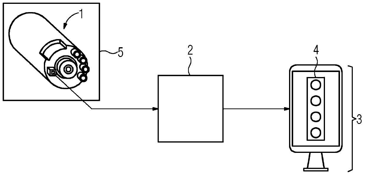
[0047] figure 1 The configuration of the system is shown, which includes the spindle 1 of the machine tool 5 , the device 2 and the visualization component 3 . The sensor data of the spindle 1 are detected by the acquisition means of the device 2 and analyzed in the processing unit of the device 2 by means of artificial intelligence. The processing means determines the spindle state from the analysis. The output means of the device 2 transmit the determined spindle state to the visualization means 3 . The visualization component 3 is embodied as a display. The signal light 4 on the visualization member 3 realizes four types of display: "permanent permission", "medium-term permission", "short-term permission" and "not allowed".

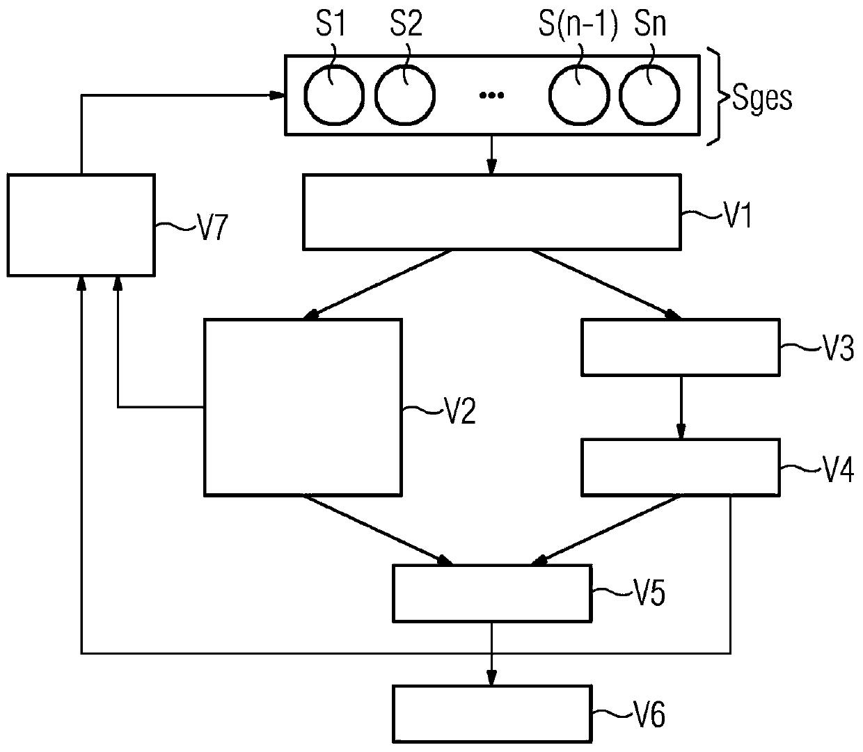
[0048] figure 2 The flow of the method is shown. First, the signal Sges is detected by the sensor. Here, for example, the spindle temperature S1 , the spindle torque S2 , the spindle force S(n−1) and the spindle speed Sn can be detected. Howeve...


PUM


Abstract

The invention relates to a device (2) and to a method for determining the status of a spindle (1) of a machine tool (5). The device (2) comprises a sensing means, which serves to acquire sensor data on the spindle (1), a processing unit, which is embodied in such a way it analyses the acquired sensor data by means of artificial intelligence and defines a spindle status on the basis thereof, and anoutput means for outputting the determined spindle status.

Description

technical field [0001] The invention relates to a device and a method for determining the state of a spindle of a machine tool spindle. Background technique [0002] During the operation of a machine tool spindle (also referred to as a tool spindle), unexpected errors may occur due to different reasons. It is possible, for example, that if the main shaft is operated for a longer period of time at an increased load level, the main shaft fails prematurely and thus before the end of its intended service life. Today's systems do not have an interface capable of displaying data describing the current state of the spindle. Therefore, the actual load on the spindle or the increased risk of failure cannot be determined with the aid of objective measurements. [0003] Currently, the spindle state is estimated based on the machine tool operator's experience. Contents of the invention [0004] The object of the invention is to improve such machine tools. [0005] This object is a...

Claims


Application Information

Patent Timeline
Patent Type & Authority Applications(China)
IPC IPC(8): G05B19/406B23Q17/00
CPCG05B19/406G05B2219/33002G05B2219/33296G05B2219/37226B23Q5/10G05B2219/37343G05B2219/37525G06N3/045
Inventor 弗洛里安·比特纳费利克斯·布根辛费利克斯·布茨乔治·多马施克迈克尔·黑尔比希菲利普·西格尔维尔纳·福姆·埃塞
Owner SIEMENS AG
Why Eureka
Try Eureka