Sandstone manufacturing device
A technology for manufacturing devices and sand and gravel, applied in the field of sand and gravel manufacturing devices, can solve problems such as inability to apply processing conditions, and achieve the effects of ensuring processing speed and pulverizing effect.
- Summary
- Abstract
- Description
- Claims
- Application Information
AI Technical Summary
Problems solved by technology
Method used
Image
Examples
specific Embodiment approach 1
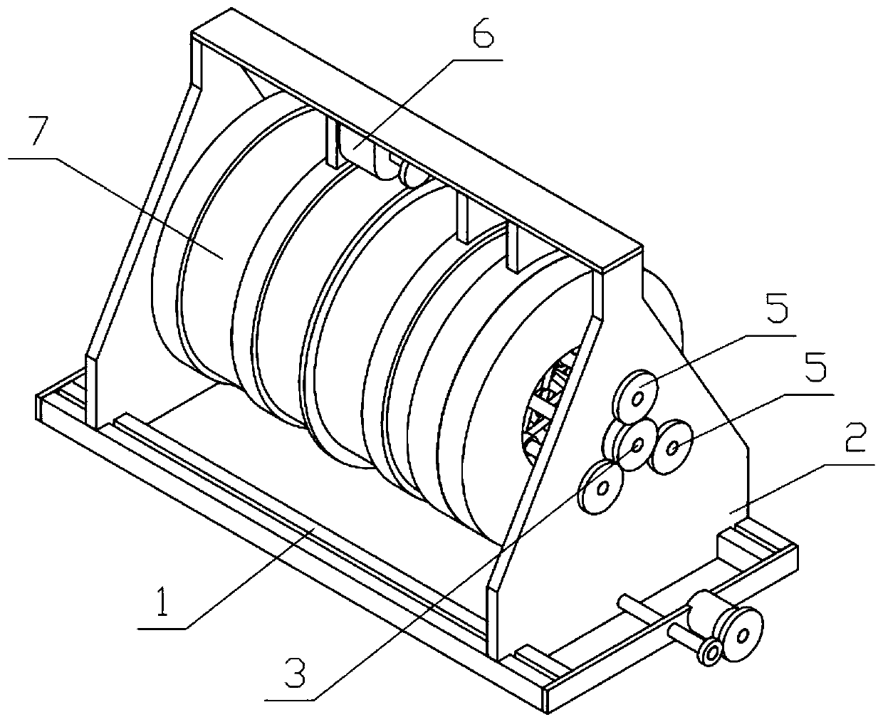
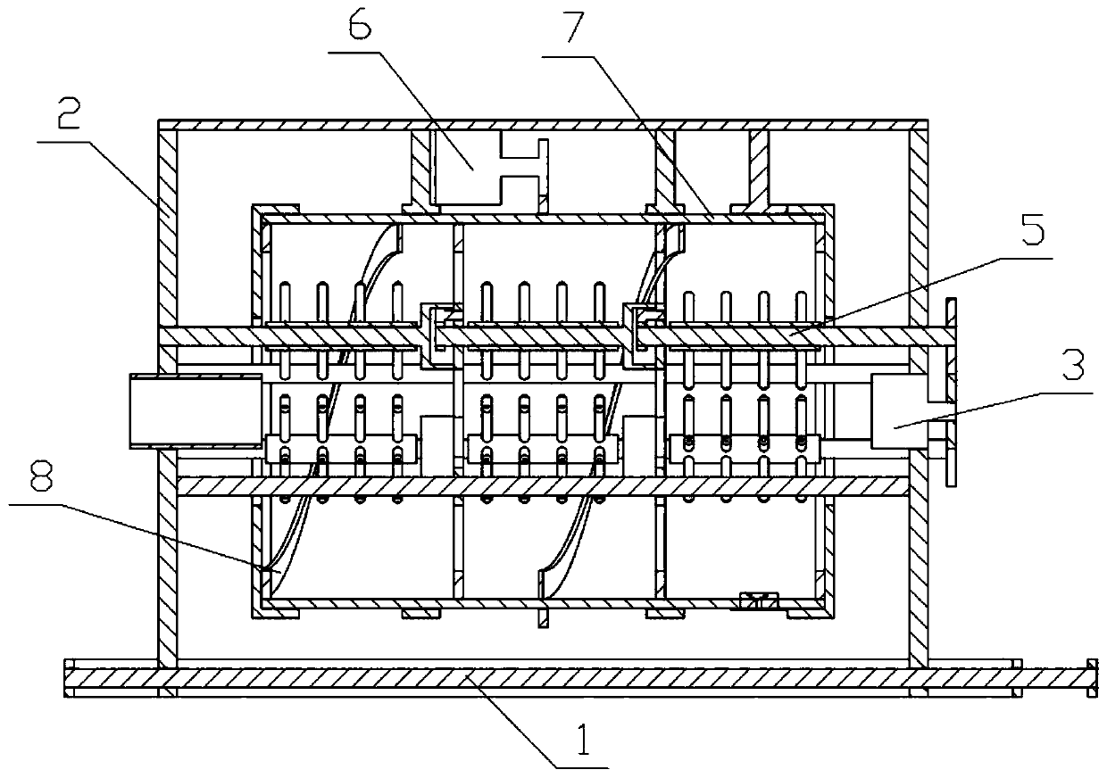
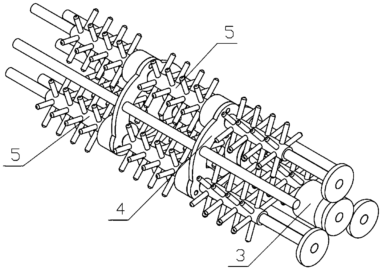
[0033] Combine below Figure 1-11Description of this embodiment, a gravel manufacturing device, including a sliding bracket 1, a device bracket 2, a power motor 3, a rotating bracket 4, a crushing mechanism 5, a rotating motor 6, a crushing cylinder 7 and a pushing mechanism 8, the sliding bracket 1 A device support 2 is connected on the device support 2, a power motor 3 is fixedly connected on the device support 2, a rotating support 4 is fixedly connected on the device support 2, and a plurality of crushing mechanisms 5 are connected in rotation on the device support 2, and a plurality of crushing mechanisms 5 are all connected with the power The motor 3 is meshed and driven, and a plurality of crushing mechanisms 5 are rotatably connected to the rotating bracket 4, the rotating motor 6 is fixedly connected to the device bracket 2, and the crushing cylinder 7 is rotatably connected to the device bracket 2, and the crushing cylinder 7 and the rotating motor 6 are meshed for tr...
specific Embodiment approach 2
[0035] Combine below Figure 1-11 Describe this embodiment, this embodiment will further explain the first embodiment, the sliding bracket 1 includes a sliding track 1-1, a connecting plate I1-2, a reciprocating screw rod 1-3 and a reciprocating motor 1-4, the sliding track 1- 1 There are two, the front and rear ends of the two slide rails 1-1 are fixedly connected with connecting plates I1-2, and the two connecting plates I1-2 are connected with reciprocating screw rods 1-3 in rotation, one side A reciprocating motor 1-4 is fixedly connected to the connecting plate I1-2, and the reciprocating motor 1-4 and the reciprocating screw mandrel 1-3 are transmission connected.
specific Embodiment approach 3
[0037] Combine below Figure 1-11 Describe this embodiment, this embodiment will further explain the second embodiment, the device bracket 2 includes a support plate I2-1, a connecting plate II2-2, a support plate II2-3, a feeding cylinder 2-4, and an installation ring I2 -5. Blocking the arc plate 2-6 and the arc hole 2-7, there are two supporting plates I2-1, and the upper ends of the two supporting plates I2-1 are fixedly connected with the connecting plate II2-2, the connecting plate The lower end of II2-2 is fixedly connected with the installation ring I2-5, the front side of the lower end of the connection plate II2-2 is fixedly connected with the blocking arc plate 2-6, and the lower end of the blocking arc plate 2-6 is provided with an arc hole 2- 7. The feeding cylinder 2-4 is fixedly connected to the support plate Ⅱ2-3 on the rear side, and the left and right sides of the two support plates Ⅰ2-1 are respectively slidably connected to the two sliding rails 1-1. The tw...
PUM
 Abstract
Description
Claims
Application Information
 - R&D
- Intellectual Property
- Life Sciences
- Materials
- Tech Scout
- Unparalleled Data Quality
- Higher Quality Content
- 60% Fewer Hallucinations
Browse by: Latest US Patents, China's latest patents, Technical Efficacy Thesaurus, Application Domain, Technology Topic, Popular Technical Reports.
© 2025 PatSnap. All rights reserved.Legal|Privacy policy|Modern Slavery Act Transparency Statement|Sitemap|About US| Contact US: help@patsnap.com


