
Position detection device and vehicle

A detection device and vehicle technology, applied in the direction of measuring device, electromagnetic measuring device, mechanical measuring device, etc., can solve the problems of real-time monitoring and extrusion of unfavorable vehicle load, the axle and frame are far away from the rotating arm, and complex working conditions, etc. , to achieve stable detection performance and results, prolong the service life of the detection, and accurately detect the vehicle load

Pending Publication Date: 2020-03-10
广东利安达科技有限公司
View PDF0 Cites 2 Cited by
  • Summary
  • Abstract
  • Description
  • Claims
  • Application Information

AI Technical Summary

Problems solved by technology

[0006] Based on this, some vehicle load detection equipment came into being, such as the weighbridge, which determines the load weight by weighing the weight of the vehicle before and after loading. However, the weighbridge is expensive and the installation location is fixed, and the vehicle needs to be driven to the weighbridge. Weighing is inconvenient to use, and it is also not conducive to real-time monitoring of vehicle load capacity
[0007] In order to solve the above problems, in the prior art, a rotating arm is connected between the axle and the frame, and the distance change between the axle and the frame is converted into the angle change of the rotating arm relative to the axle (or frame) , and then use the angle sensing device to detect the angle of the pivot arm relative to the axle (or frame) to detect the way the vehicle is loaded; however, the driving and use conditions of the vehicle (especially the truck) are often complicated, and the vehicle is in poor road conditions. When driving on a rough road, the distance between the axle and the frame will vary depending on the potholes on the road surface; Pulling on the arm, causing damage to the arm and angle sensing device

Method used


Image

  • Position detection device and vehicle
  • Position detection device and vehicle
  • Position detection device and vehicle

Examples


Embodiment 1

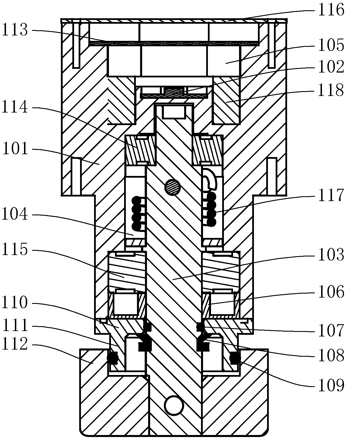
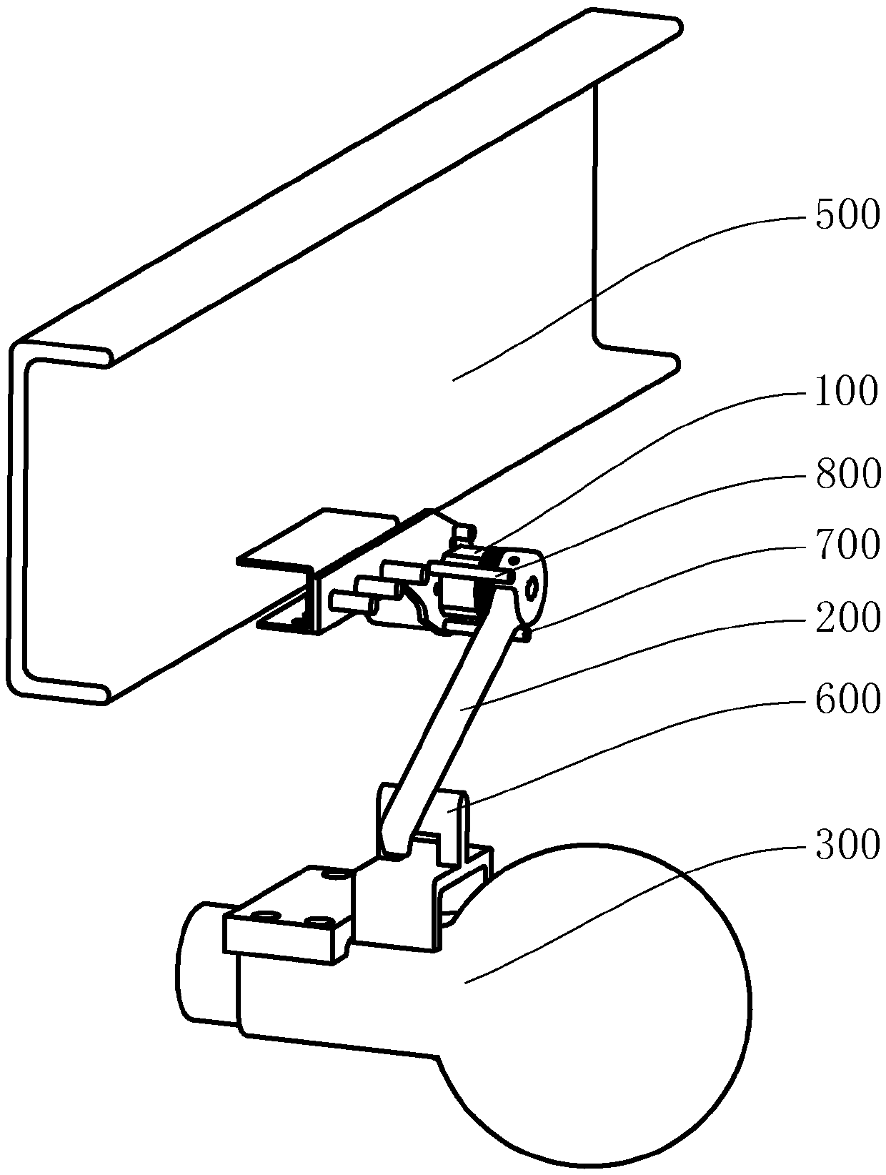
[0062] Please refer to figure 1 and figure 2 , the vehicle of this embodiment includes the vehicle axle 300 and the vehicle frame 500, and also includes the control device and the position detection device of any one of the foregoing; the pretension device is the torsion spring 117 connecting the housing 101 and the rotating shaft 103; the angle sensing device The casing 101 of 100 is fixed on the vehicle frame 500, the rotating arm 200 is close to the axle 300 under the action of the pre-tensioning device, and the control device is electrically connected with the angle detection device 100; 300 distance changes, and then cause the rotation of the rotating arm 200 relative to the angle sensing device 100, and the angle sensing device 100 obtains the rotation angle of the rotating arm 200; in this series of causal relationships, for a specific vehicle, the vehicle The load, the distance between the axle 300 and the frame 500, and the rotation angle of the pivot arm 200 relati...

Embodiment 2

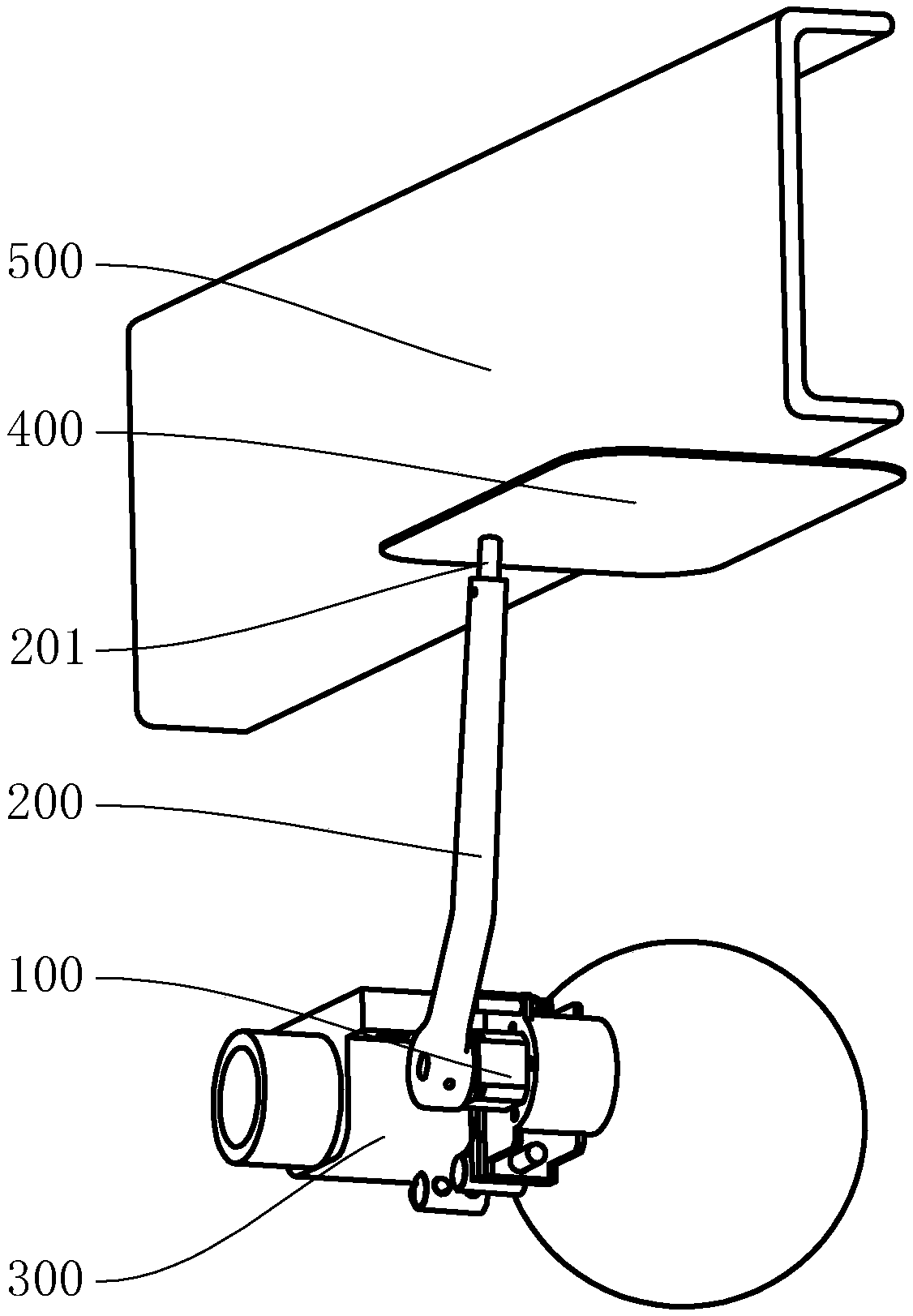
[0069] Please refer to figure 1 and image 3 , the housing 101 of the angle sensing device 100 is fixed on the axle 300, and the rotating arm 200 is closely attached to the vehicle frame 500 under the action of the pre-tensioning device. Relative to the angle change of the magnetic field detection device, the distance between the vehicle frame 500 and the vehicle axle 300 can be detected by detecting the rotation angle of the rotating arm 200, and then the load of the vehicle can be determined; Instead of using direct connection, a pretensioning device is used to make the rotating arm 200 close to the frame 500. Therefore, when the distance between the axle 300 and the frame 500 changes due to bumps, the rotating arm 200 will not be pulled, and the rotating arm 200 will not be pulled. Pull damage.

[0070] Please refer to image 3 , the angle sensing device 100 is fixed on the side of the axle 300 ; the angle sensing device 100 is prevented from being squeezed and damaged w...

Embodiment 3

[0075] Please refer to Figure 4 , the same as the setting position of the angle sensing device 100 on the axle 300 or the vehicle frame 500, the friction frame 600 is located on the side of the vehicle axle 300 to prevent the friction frame 600 from being squeezed when the vehicle frame 500 and the vehicle axle 300 are relatively close together damage.

[0076] Please refer to Figure 4 , as a preference, the rotation path of the rotating arm 200 is provided with the first limiting member 700 and the second limiting member is not provided, the first limiting member 700 is arranged on the path of the rotating arm 200 swinging to the friction frame 600, due to the preset Due to the existence of the tightening device, the rotating arm 200 is normally close to the friction frame 600 and has a tendency to rotate towards the friction frame 600. The distance will increase, so that the length of the rotating arm 200 is not enough to contact the friction frame 600. At this time, the...


PUM


Abstract

A position detection device relates to the technical field of on-vehicle weighing machinery, and comprises an angle sensing device, a rotating arm and a pre-tightening device; the rotating arm is rotatably connected to the angle sensing device, one end of the pre-tightening device is connected to the rotating arm or connected to a common foundation together with the rotating arm, and the other endof the pre-tightening device is connected to the angle sensing device or connected to the common foundation together with the angle sensing device. The vehicle adopts the position detection device. The pre-tightening device is additionally arranged, so that the position detection device has a stable detection reference, and the detection results of each time are more accurate; in addition, the rotating arm and the position detection device can be prevented from being pulled apart when the distance between the two parts is increased, and the position detection device can be suitable for detecting the position relation of the two parts with the large relative movement range or the unstable position relation; according to the invention, the position detection device cannot be damaged due tothe change of the distance between an axle and a frame.

Description

technical field [0001] The invention relates to the technical field of on-vehicle weighing machinery, in particular to a position detection device and a vehicle. Background technique [0002] In the prior art, an angle sensing device can be used to detect the relative positional relationship (such as angle relationship and distance relationship) of two relatively moving parts (such as the first part and the second part), for example, the angle sensor device is installed on the first part , the rotating arm that rotates relative to the angle sensing device is hinged on the second part, and when the second part moves relative to the first part, the rotating arm is driven to rotate, and the angle sensing device is used to detect the rotation angle of the rotating arm relative to the angle sensing device. The specific positional relationship (angular relationship or distance relationship in a specific direction) between a component and a second component has a one-to-one corresp...

Claims


Application Information

Patent Timeline
Patent Type & Authority Applications(China)
IPC IPC(8): G01G19/08G01B7/00G01B7/30
CPCG01B5/0025G01B7/003G01B7/30G01G19/08
Inventor 黄采枫李安兵张浩张佳俊黄海柔黄东辉付国源陈茜张佳敏张立安
Owner 广东利安达科技有限公司
Learn More