Protective components, covers and cases
A component and protective layer technology, applied in battery pack parts, structural parts, electrical components, etc., can solve the problems of potential safety hazards in battery modules or battery packs, and achieve the effect of ensuring the safety of use and improving the safety of use.
- Summary
- Abstract
- Description
- Claims
- Application Information
AI Technical Summary
Problems solved by technology
Method used
Image
Examples
no. 1 example
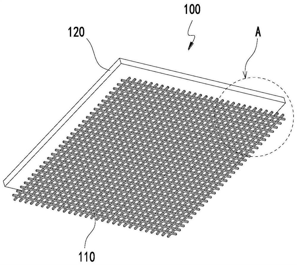
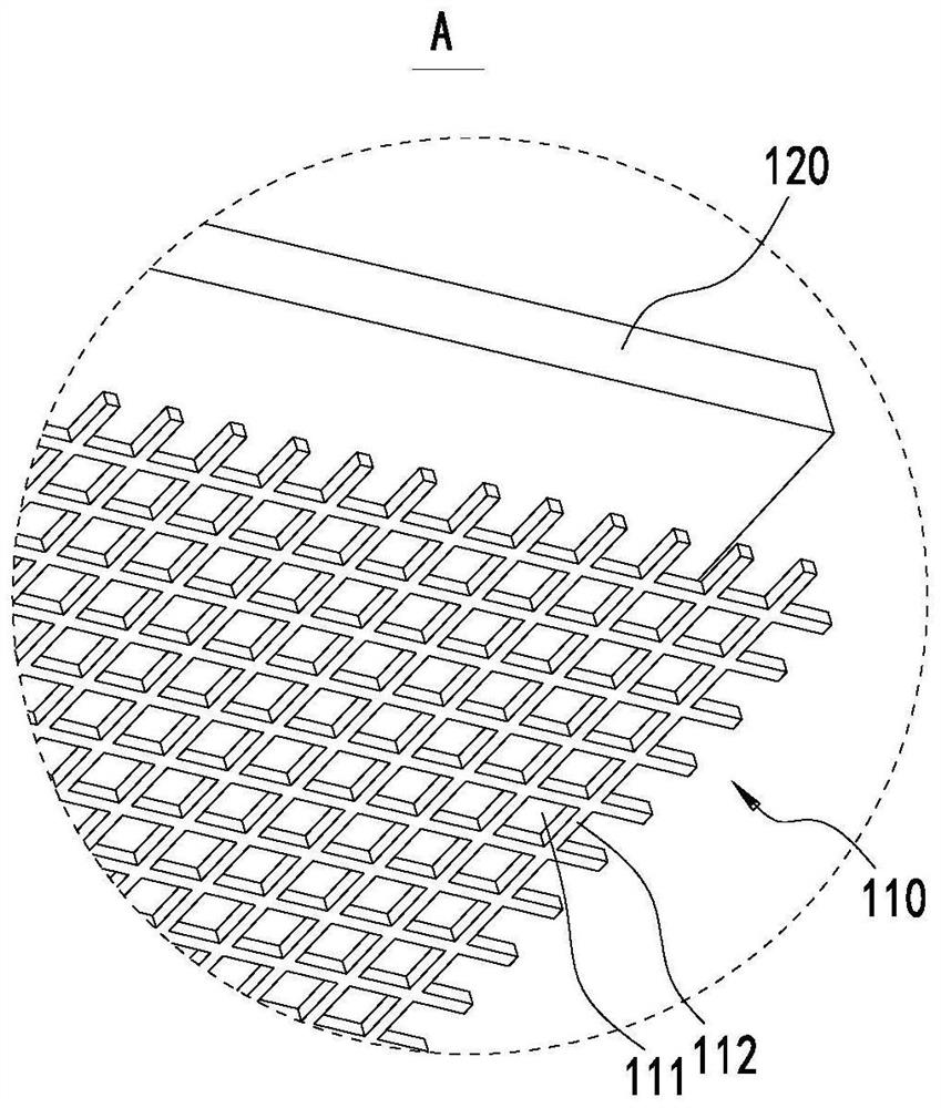
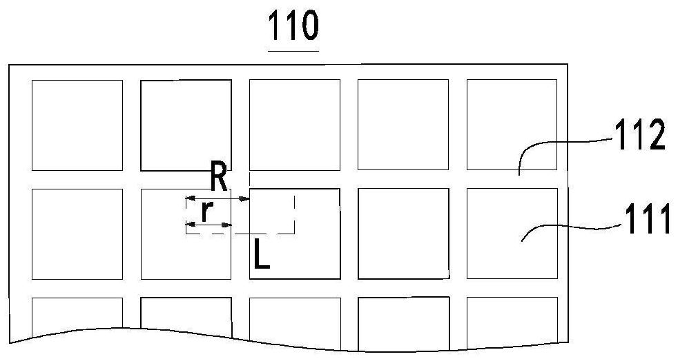
[0042] see Figure 1 to Figure 6 As shown, the particle blocking layer 110 included in the protection assembly 100 of this embodiment is a network structure with a predetermined thickness. Each particle blocking unit includes a hole 111 extending in the thickness direction of the particle blocking layer 110 and a grid 112 surrounding the hole 111. The hole 111 is a concave portion of the particle blocking unit, and the grid 112 is a convex portion of the particle blocking unit, so that the particle blocking unit is configured as a structure with concave and convex. The hole walls of the holes 111 and / or the grid 112 can be used to block high-temperature particles or enrich high-temperature particles, so as to achieve the function of intercepting and blocking high-temperature particles.
[0043] In one embodiment, the grid 112 may be a connection between two adjacent holes 111 . The hole wall of the hole 111 and the grid 112 can form an interception effect on the high-tempera...
Embodiment 1
[0063] The particle blocking unit included in the particle blocking layer 110 of this embodiment is a network structure. The hole 111 comprised by the particle blocking unit has an aperture r ranging from 0.038 mm to 4.75 mm. The particle blocking layer 110 is made of barbed wire. The thickness of the isolation protection layer 120 ranges from 0.5mm to 10mm, and its material is melamine foam. The protection assembly 100 of this embodiment includes the above-mentioned particle barrier layer 110 and isolation protection layer 120. The protective assembly 100 of this embodiment is tested in practice, and when the pressure relief element 92 bursts, the cover of the battery module 90 or the case of the battery pack will not melt through.
Embodiment 2 to 13
[0065] Embodiments 2 to 13 are different from some parameters of Embodiment 1, but can achieve the same technical effect. The protective assembly 100 of various embodiments has been tested in practice. When the pressure relief element 92 bursts, the cover of the battery module 90 or the case of the battery pack will not melt through. See Table 1 for details:
[0066] Table 1
[0067]
[0068] In addition, the protection test of the protection assembly 100 of the embodiment of the present invention:
[0069] Fully charge the battery module 90 or the battery pack. The pressure relief element 92 of the secondary battery 91 is facing the cover of the battery module 90, and the pressure relief element 92 of the battery module 90 is facing the box of the battery pack or the pressure relief element of the secondary battery 91 included in the battery module. 92 is facing the casing of the battery pack. Then trigger the secondary battery 91 out of control with heating, acupunctu...
PUM
| Property | Measurement | Unit |
|---|---|---|
| thermal conductivity | aaaaa | aaaaa |
| thermal resistance | aaaaa | aaaaa |
| thickness | aaaaa | aaaaa |
Abstract
Description
Claims
Application Information
 - R&D
- Intellectual Property
- Life Sciences
- Materials
- Tech Scout
- Unparalleled Data Quality
- Higher Quality Content
- 60% Fewer Hallucinations
Browse by: Latest US Patents, China's latest patents, Technical Efficacy Thesaurus, Application Domain, Technology Topic, Popular Technical Reports.
© 2025 PatSnap. All rights reserved.Legal|Privacy policy|Modern Slavery Act Transparency Statement|Sitemap|About US| Contact US: help@patsnap.com


