Plasma temperature distribution measurement system

A plasma and temperature distribution technology, applied in the field of plasma, which can solve the problems of inaccurate measurement, non-destructive, accurate, difficult and unrealistic measurement, etc.

Inactive Publication Date: 2020-03-10
CHINA PETROLEUM & CHEM CORP +1
View PDF11 Cites 2 Cited by
  • Summary
  • Abstract
  • Description
  • Claims
  • Application Information

AI Technical Summary

Problems solved by technology

Since the plasma itself is in a highly ionized state and is in a complex electromagnetic coupling state, it is extremely difficult to measure the temperature parameters of the plasma state material in a non-destructive, accurate and effective manner. For example, when using an intrusive measurement method, once a sensor probe enters The plasma region will disturb the plasma form, and the plasma state parameters near the probe will become better, resulting in inaccurate and untrue measurements
In addition, under high voltage discharge conditions, intrusive measurements tend to damage the sensor and are not easy to implement
Non-contact measurement can only measure the surface temperature of the plasma generator shell, but it is difficult to measure the temperature distribution inside the plasma
[0003] Temperature parameters are very important parameter data for plasma generator performance characterization, material selection, structural design, etc., so there is a lack of a technology that can accurately measure the plasma temperature distribution in the prior art

Method used


Image

  • Plasma temperature distribution measurement system
  • Plasma temperature distribution measurement system

Examples


Embodiment Construction

[0029] The specific implementation manners of the embodiments of the present invention will be described in detail below in conjunction with the accompanying drawings. It should be understood that the specific implementation manners described here are only used to illustrate and explain the embodiments of the present invention, and are not intended to limit the embodiments of the present invention.

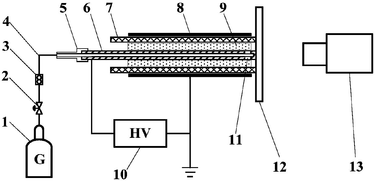
[0030] figure 1 is a structural diagram of a plasma temperature distribution measurement system according to an embodiment of the present invention; figure 2 is a structural diagram of a plasma temperature distribution measurement system according to another embodiment of the present invention.

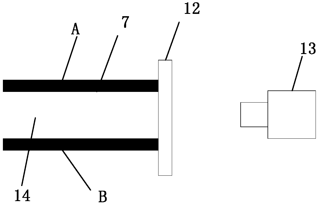
[0031] The plasma temperature distribution measurement system in one embodiment of the present invention includes: a plasma generation module, including a positive electrode A, a negative electrode B, and an insulating barrier medium 7, the positive electrode A and the negative electrod...


PUM


Abstract

The invention relates to the technical field of plasmas, and specifically relates to a plasma temperature distribution measurement system. The system comprises a plasma generating module and an infrared measurement module, wherein the plasma generating module comprises a positive electrode, a negative electrode and an insulating barrier medium, the positive electrode and the negative electrode areoppositely arranged, the insulating barrier medium is arranged between the positive electrode and the negative electrode in a spaced mode, the insulating barrier medium forms a cavity with an openingin one side, and at least one of the other side surfaces of the cavity is blocked by an infrared-transmitting blocking material; and the infrared measurement module is arranged at a position which isseparated from the side surface, which is blocked by the infrared-transmitting blocking material, of the cavity by a preset distance, and is used for measuring infrared distribution of plasmas generated in the cavity so as to measure temperature distribution of the plasmas. The plasma temperature distribution measurement system can measure the temperature distribution of the plasmas by measuringthe infrared distribution of the plasmas, so that non-destructive and accurate temperature distribution measurement can be realized.

Description

technical field [0001] The invention relates to the field of plasma technology, in particular to a plasma temperature distribution measurement system. Background technique [0002] Plasma is the fourth form of matter. In scientific research and practical applications, gas discharge is the main form of plasma generation. Since the plasma itself is in a highly ionized state and is in a complex electromagnetic coupling state, it is extremely difficult to measure the temperature parameters of the plasma state material in a non-destructive, accurate and effective manner. For example, when using an intrusive measurement method, once a sensor probe enters In the plasma region, the plasma form will be disturbed, and the plasma state parameters near the probe will become better, resulting in inaccurate and untrue measurements. In addition, under high-voltage discharge conditions, intrusive measurements tend to damage the sensor and are not easy to implement. Non-contact measurement...

Claims


Application Information

Patent Timeline
Patent Type & Authority Applications(China)
IPC IPC(8): H05H1/00
CPCH05H1/0043
Inventor 王世强唐诗雅牟善军刘全桢关银霞牟洪祥
Owner CHINA PETROLEUM & CHEM CORP
Why Eureka
Try Eureka