Detachable splash-proof mechanism

A detachable, splash-proof plate technology, applied in the field of machine tool bed, can solve the problems of inconvenient cleaning of splash-proof plates and deflectors, and achieve the effect of reducing the probability of contaminating the positioning plate

Active Publication Date: 2020-03-13
CHONGQING HONGGANG CNC MACHINE TOOL
View PDF6 Cites 0 Cited by
  • Summary
  • Abstract
  • Description
  • Claims
  • Application Information

AI Technical Summary

Problems solved by technology

[0005] The purpose of the present invention is to provide a detachable splash-proof mechanism to solve the problem of inconvenient cleaning of the splash-proof plate and deflector in the prior art

Method used


Image

  • Detachable splash-proof mechanism
  • Detachable splash-proof mechanism
  • Detachable splash-proof mechanism

Examples


Embodiment 1

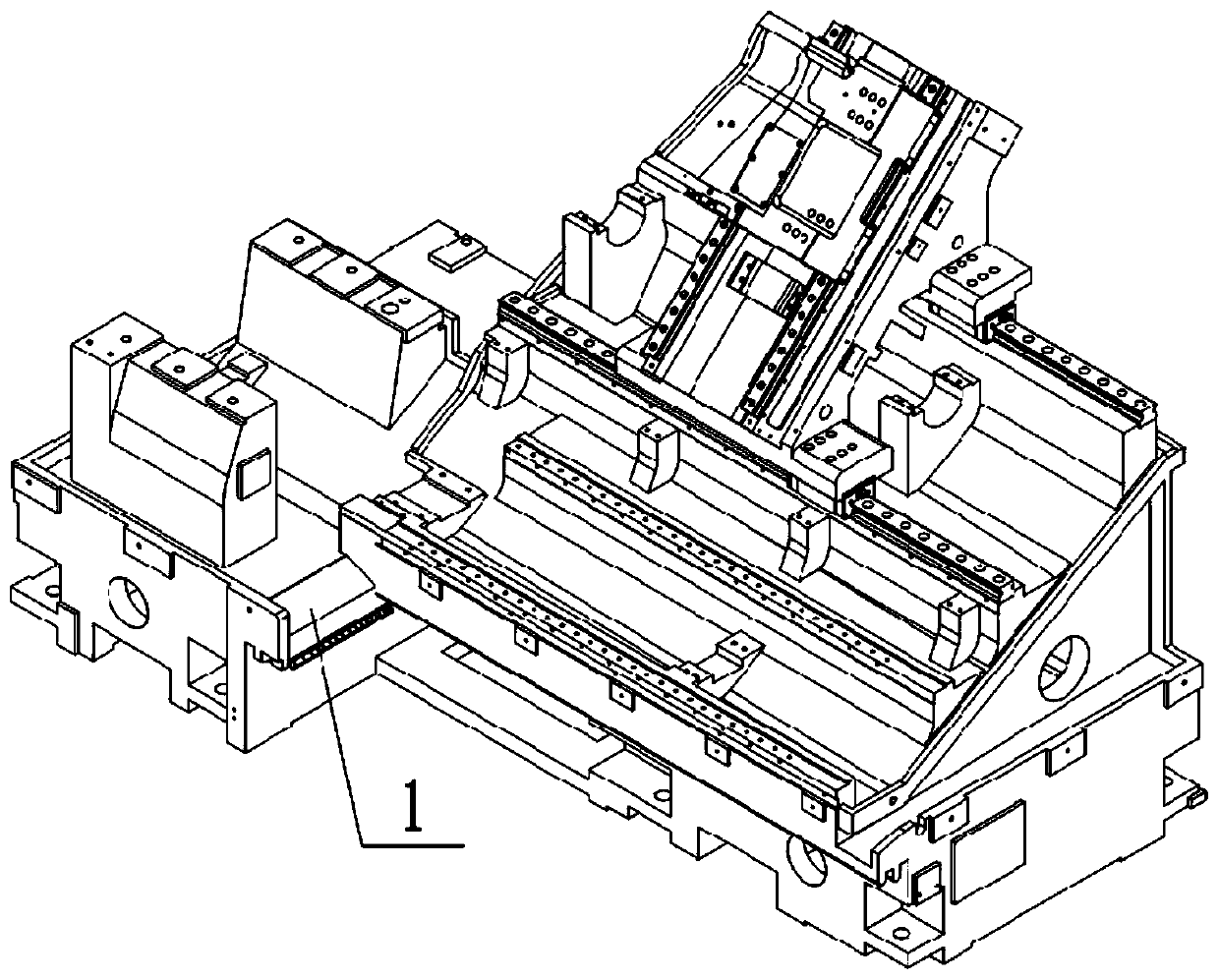
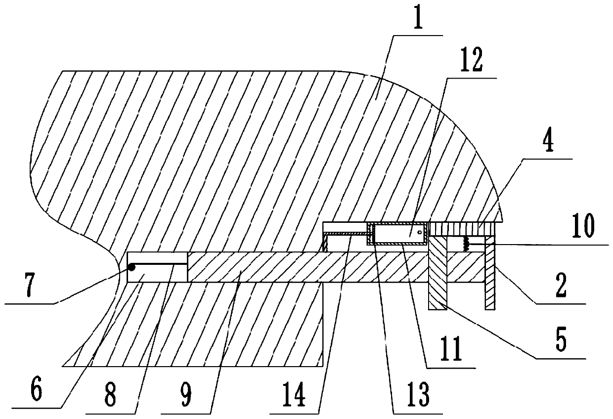
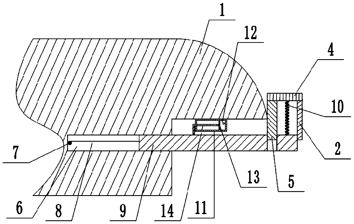
[0036] The detachable anti-splash mechanism is mainly composed of a chute 6, a positioning plate 9, a spring 10, an anti-splash unit, a flushing unit and a reset unit. combined with figure 1 And attached figure 2 As shown, the chute 6 is provided on the side wall of the machine tool, and a positioning plate 9 is horizontally slidably connected in the chute 6. The side of the locating plate 9 away from the chute 6 is provided with a positioning hole, and a spring 10 is welded on the positioning plate 9. , the spring 10 is located on the right side of the positioning hole.

[0037] The reset unit is arranged in the chute 6 for resetting the positioning plate 9; the reset unit is mainly composed of a rotating shaft 7, a torsion spring and a pull rope 8, the rotating shaft 7 is connected in the chute 6 in rotation, and one end of the torsion spring is fixed on the rotating shaft 7 On, the other end of torsion spring is fixed on the chute 6 inner wall. One end of stay cord 8 is...

Embodiment 2

[0045] The difference between this embodiment and Embodiment 1 is: in this embodiment, in combination with the attached Figure 4 And attached Figure 5 As shown, the deflector 2 is mainly composed of a guide portion 21 and a flow diversion portion 22, and a plurality of leakage holes 3 are evenly distributed on the flow diversion portion 22. The splitter part 22 is arranged obliquely, and the direction of inclination is inclined from the guide part 21 to the direction away from the guide part 21, and the inclination angle is 15°-25°. During operation, the two ends of the splitter part 22 are respectively located under the two sides of the cooling water artesian part 1 .

[0046] In this solution, the guide part 21 can guide the flow direction of the cooling water, so that the cooling water flowing down from the cooling water flow part 1 flows into the water tank along the deflector 2 . The leak hole 3 on the splitter 22 can divide the cooling water flowing to the splitter 2...


PUM

PropertyMeasurementUnit
Slopeaaaaaaaaaa

Abstract

The present application relates to the technical field of machine tool bodies, and discloses a detachable splash-proof mechanism. The mechanism includes a sliding groove arranged in the side wall of amachine tool, a positioning plate is slidably connected in the sliding groove, and the positioning plate is provided with a positioning hole and a spring; the positioning plate is detachably connected to a splash-proof unit, the splash-proof unit includes a flow guide plate and a splash-proof plate, the top of the flow guide plate and the top of the splash-proof plate are connected to a horizontal plate together, and the horizontal plate abuts the top of the spring; and the splash-proof plate is slidably connected in the positioning hole, and one end, far away from the sliding groove, of thepositioning plate abuts the flow guide plate. The mechanism provided by the solution realizes the detachable installation of the splash-proof component, is convenient for workers to take off for cleaning, has a simple and convenient installation method, is convenient to use, and has good stability.

Description

technical field [0001] The invention belongs to the technical field of machine tool beds. Background technique [0002] Machine tools mainly refer to lathes and milling machines. Machine tools are widely used in the machining industry for the multi-variety processing of sophisticated and complex rotating parts. [0003] Existing machine tools need to use cooling water in the process of processing workpieces, and the cooling water gradually flows to the cooling water artesian part at the low point of the machine tool, and then flows into the water tank located under the middle of the machine tool through the cooling water artesian part. The cutterhead running at high speed drives the cooling water to the water tank or the low point of the machine tool at high speed, and flows into the water tank along the cooling water artesian part of the machine tool. Due to the high speed of the cooling water flowing on the self-flowing surface of the cooling water, the cooling water fall...

Claims


Application Information

Patent Timeline
IPC IPC(8): B23Q11/08B23Q11/00
CPCB23Q11/00B23Q11/08
Inventor 王小玲汪传宏汪洋刘辉饶贝宁
Owner CHONGQING HONGGANG CNC MACHINE TOOL
Why Eureka
Try Eureka