
Perforating device for new material processing

A drilling device and new material technology, applied in the field of material processing, can solve the problems of inconvenient replacement of drill bits, etc., and achieve the effect of convenient installation, convenient disassembly, and simple operation

Inactive Publication Date: 2020-03-13
SUZHOU ZHIRUI PHOTOELECTRIC MATERIAL TECH CO LTD
View PDF1 Cites 3 Cited by
  • Summary
  • Abstract
  • Description
  • Claims
  • Application Information

AI Technical Summary

Problems solved by technology

[0002] Research on new materials has always been the subject of scientific research projects in my country. Before new materials are used, new materials need to be processed. The most common way to process new materials is to drill holes. The traditional drilling device is inconvenient to replace the drill bit. Therefore, we propose a A kind of punching device for new material processing is used to solve the above problems
[0003] In the prior art, the publication number is CN108312227A, which discloses a new material punching device, which includes a horizontally arranged bottom plate. A top plate is horizontally provided on the top of the vertical board, a mounting plate is horizontally provided at the position between the two vertical boards, first electric telescopic rods are vertically provided at both ends of the bottom surface of the top board, and the bottom ends of the two first electric telescopic rods are horizontally provided. There are guide rods, both ends of the top surface of the mounting plate are provided with guide plates, and the guide rods are set in the guide holes of the guide plate, and one end of the bottom surface of the guide rods is provided with a vertical rod, but this new type does not involve how to facilitate the installation and disassembly of the drill bit , there is room for improvement

Method used


Image

  • Perforating device for new material processing
  • Perforating device for new material processing
  • Perforating device for new material processing

Examples


Embodiment Construction

[0019] The following will clearly and completely describe the technical solutions in the embodiments of the present invention with reference to the accompanying drawings in the embodiments of the present invention. Obviously, the described embodiments are only some, not all, embodiments of the present invention.

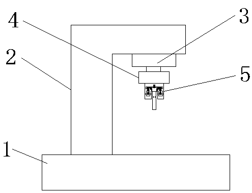
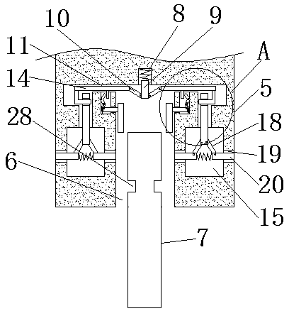
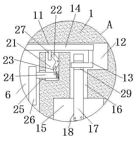
[0020] refer to Figure 1-3 , a drilling device for new material processing, comprising a base 1, an L-shaped column 2 is fixedly installed on the top side of the base 1, a telescopic hydraulic cylinder 3 is fixedly installed on the bottom side of the L-shaped column 2, and the telescopic shaft of the telescopic hydraulic cylinder 3 A motor 4 is fixedly installed, and the output shaft of the motor 4 is fixedly installed with a rotating shaft 5 through a coupling. The bottom end of the rotating shaft 5 is provided with a mounting groove 6, and a drill bit 7 is arranged in the mounting groove 6, and the bottom side of the drill bit 7 extends to Outside the installation...


PUM


Abstract

The invention discloses a perforating device for new material processing. The perforating device for new material processing comprises a base; an L-shaped post is fixedly mounted on the top side of the base; a telescopic hydraulic cylinder is fixedly mounted on the bottom side of the L-shaped post; a motor is fixedly mounted on a telescopic shaft of the telescopic hydraulic cylinder; a rotating shaft is fixedly mounted on an output shaft of the motor through a shaft coupling; a mounting groove is formed in the bottom end of the rotating shaft; a drill bit is arranged in the mounting groove; the bottom side of the drill bit extends out of the mounting groove; a groove is formed in the inner wall of the top side of the mounting groove; an ejector rod is movably mounted in the groove; the bottom end of the ejector rod extends into the mounting groove, and two rotating rods are rotatably mounted at the bottom end of the ejector rod; and the moving grooves which are symmetric based the drill bit are formed in the inner walls of the two sides of the mounting groove. The perforating device for new material processing is easy to operate; when the drill bit is worn or broken, the drill bitcan be taken out by pressing two clamping rods far from each other; the detachment of the drill bit is facilitated; a new drill bit can be fixed by vertically moving the new drill bit aligning with the mounting groove; the mounting of the new drill bit is facilitated; and the demands of people are met.

Description

technical field [0001] The invention relates to the technical field of material processing, in particular to a punching device for new material processing. Background technique [0002] Research on new materials has always been the subject of scientific research projects in my country. Before new materials are used, new materials need to be processed. The most common way to process new materials is to drill holes. The traditional drilling device is inconvenient to replace the drill bit. Therefore, we propose a A kind of punching device for new material processing solves the above problems. [0003] In the prior art, the publication number is CN108312227A, which discloses a new material punching device, which includes a horizontally arranged bottom plate, the top surface of the bottom plate is provided with new materials through chucks, vertical plates are arranged at both ends of the top surface of the bottom plate, and two A top plate is horizontally provided on the top of ...

Claims


Application Information

Patent Timeline
IPC IPC(8): B26F1/16B26D7/26
CPCB26D7/2614B26F1/16
Inventor 顾黎明
Owner SUZHOU ZHIRUI PHOTOELECTRIC MATERIAL TECH CO LTD
Learn More