
Elastic supporting undercarriage of fixed wing type unmanned aerial vehicle based on rack transmission

A rack drive, elastic support technology, applied in landing gear, wheeled, aircraft parts, etc., can solve the problems of shortening the service life of the drone, affecting the normal landing of the drone, and the large bearing load of the connecting shaft, reducing the Bearing load, excellent buffering and shock absorption effect, the effect of reducing impact force

Active Publication Date: 2020-03-13
湖南浩天翼航空技术有限公司
View PDF11 Cites 13 Cited by
  • Summary
  • Abstract
  • Description
  • Claims
  • Application Information

AI Technical Summary

Problems solved by technology

[0002] Landing gear is a support frame used on UAVs. Fixed-wing UAVs are small UAVs in the shape of airliners. The landing gear is a landing gear with tires. When flying in the air The landing gear will be folded into the inside of the UAV and put down when it lands; however, the traditional landing gear does not have an orientation function when it is folded. On the one hand, it will cause a large load on the coupling shaft and gears, and on the other hand, it is easy to open the range. Crossing the vertical line will affect the normal landing of the UAV, which is not conducive to use. Secondly, the cushioning and shock absorption effect is poor, and it will have a large impact on the ground when it lands, which will reduce the service life of the UAV.

Method used


Image

  • Elastic supporting undercarriage of fixed wing type unmanned aerial vehicle based on rack transmission
  • Elastic supporting undercarriage of fixed wing type unmanned aerial vehicle based on rack transmission
  • Elastic supporting undercarriage of fixed wing type unmanned aerial vehicle based on rack transmission

Examples


Embodiment Construction

[0021] In order to make the technical means, creative features, achievement goals and effects realized by the present invention easy to understand, the present invention will be further described below with reference to the specific embodiments.

[0022] In the description of the present invention, it should be noted that the terms "upper", "lower", "inner", "outer", "front end", "rear end", "two ends", "one end" and "the other end" The orientation or positional relationship indicated by etc. is based on the orientation or positional relationship shown in the accompanying drawings, and is only for the convenience of describing the present invention and simplifying the description, rather than indicating or implying that the indicated device or element must have a specific orientation, with a specific orientation. The orientation configuration and operation are therefore not to be construed as limitations of the present invention. Furthermore, the terms "first" and "second" are...


PUM


Abstract

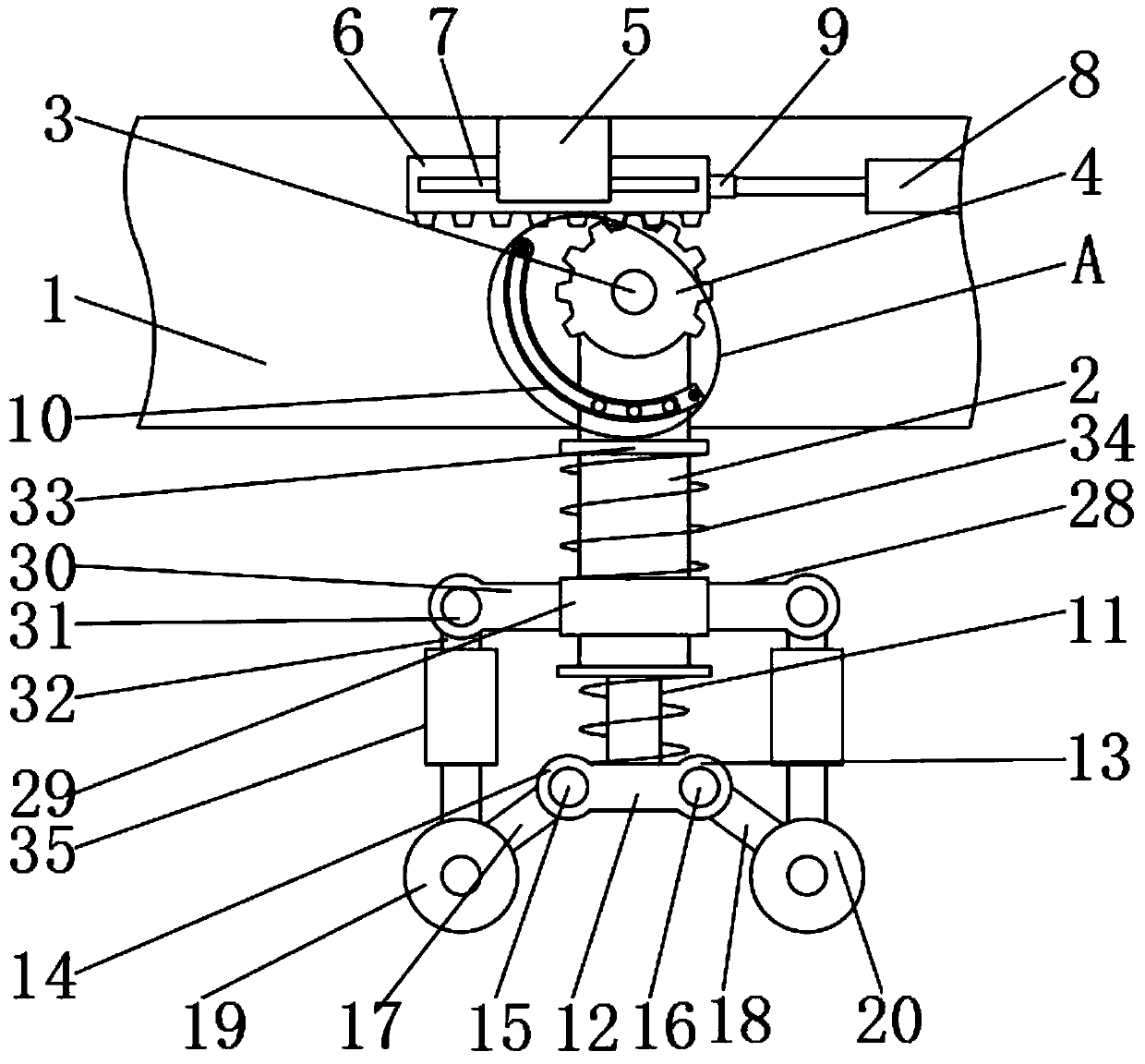
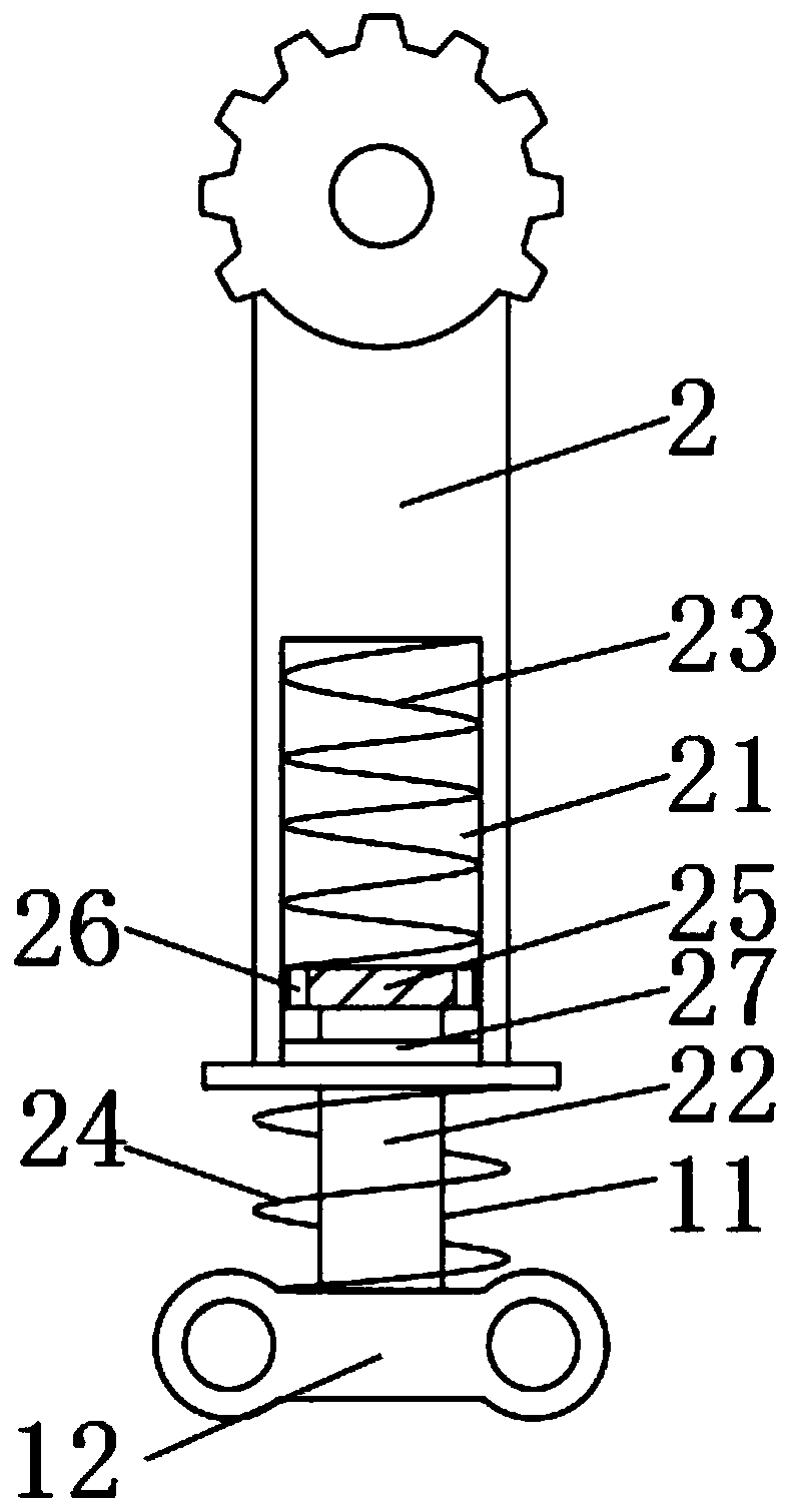
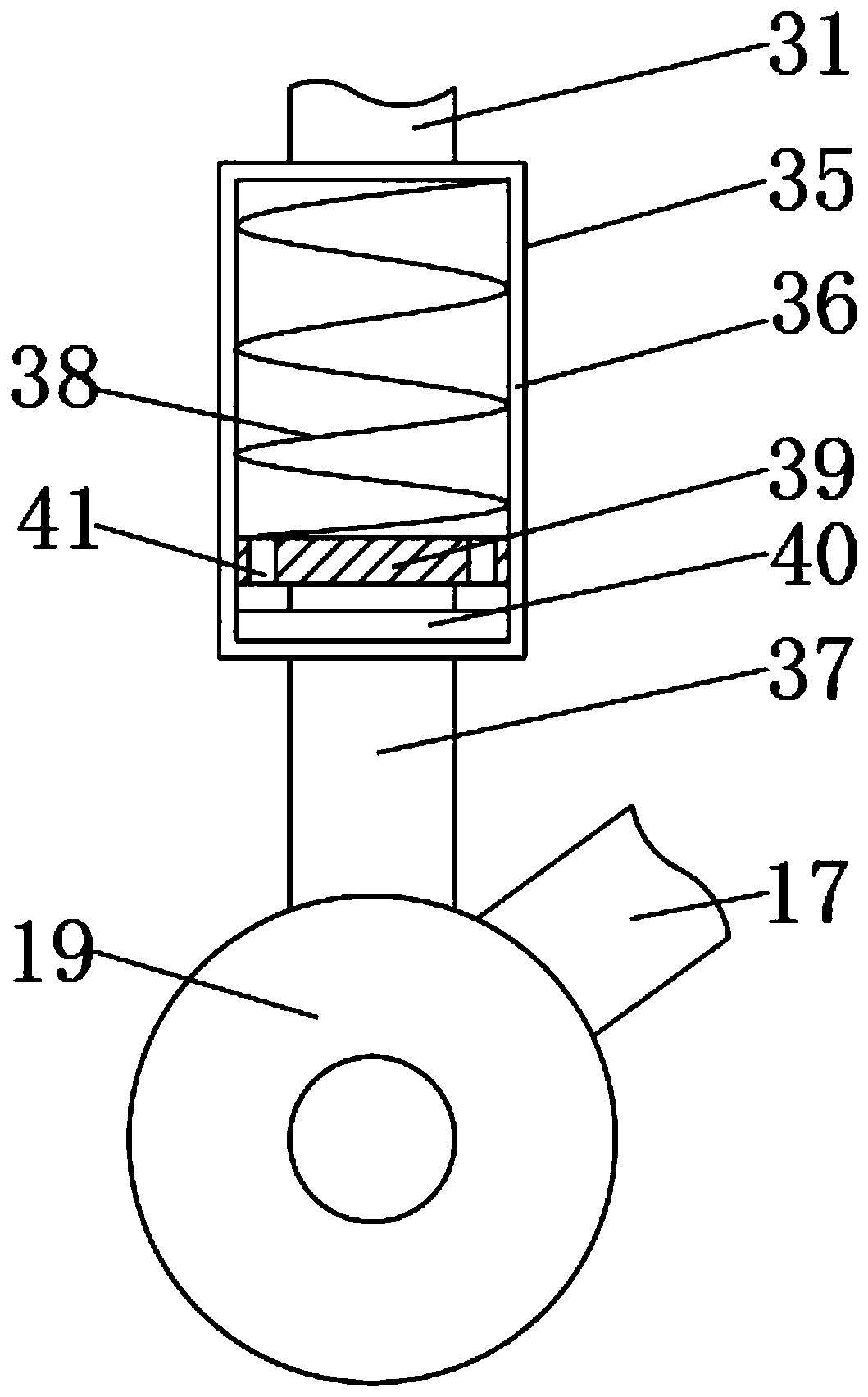
The invention discloses an elastic supporting undercarriage of a fixed wing type unmanned aerial vehicle based on rack transmission. The unmanned aerial vehicle comprises an unmanned aerial vehicle body, undercarriage main rods and electric telescopic rods. A connecting gear is fixedly mounted at the top end of the undercarriage main rod. The connecting gear is movably connected with the unmannedaerial vehicle through a rotating shaft, a fixed sliding block is fixedly installed at the upper position in the unmanned aerial vehicle, a rack is arranged at the rear portion of the fixed sliding block, a telescopic rod of the electric telescopic rod is fixedly connected with one end of the rack, and a connecting fixing piece is arranged between the telescopic rod of the electric telescopic rodand the rack. According to the elastic supporting undercarriage of a fixed wing type unmanned aerial vehicle based on rack transmission, the orientation effect can be achieved, and the bearing load ofthe rotating shaft is reduced. Meanwhile, the phenomenon that the undercarriage crosses a vertical line when being opened can be avoided. Meanwhile, the excellent damping and buffering effect is achieved, and the excellent protection effect on the unmanned aerial vehicle is achieved.

Description

technical field [0001] The invention relates to the field of landing gear, in particular to an elastically supported landing gear of a fixed-wing unmanned aerial vehicle based on rack drive. Background technique [0002] The landing gear is a frame used for support on the drone. The fixed-wing drone is a small drone similar to the shape of a passenger aircraft. Its landing gear is a landing gear with tires. When flying in the air The landing gear will be folded inside the drone and put down when it lands; however, the traditional landing gear does not have the directional function when it is folded. Crossing the vertical line will affect the normal landing of the drone, which is not conducive to use. Secondly, the buffering and shock absorption effect is poor, and when landing, it will produce a large impact force with the ground, which will reduce the service life of the drone. SUMMARY OF THE INVENTION [0003] The main purpose of the present invention is to provide an e...

Claims


Application Information

Patent Timeline
IPC IPC(8): B64C25/34B64C25/60B64C25/62
CPCB64C25/34B64C25/60B64C25/62B64C2025/345
Inventor 龚弟云
Owner 湖南浩天翼航空技术有限公司
Learn More