Flowing particle speed measuring method and system

A technology of flow velocity and measurement method, applied in the direction of fluid velocity measurement, velocity/acceleration/impact measurement, measurement device, etc., to avoid the effect of soot

Inactive Publication Date: 2020-03-13
AECC SHENYANG ENGINE RES INST
View PDF9 Cites 2 Cited by
  • Summary
  • Abstract
  • Description
  • Claims
  • Application Information

AI Technical Summary

Problems solved by technology

[0008] The purpose of this application is to provide a flow velocity measurement method and system to solve or alleviate at least one of the problems in the background art

Method used


Image

  • Flowing particle speed measuring method and system
  • Flowing particle speed measuring method and system
  • Flowing particle speed measuring method and system

Examples


Embodiment Construction

[0044] In order to make the purpose, technical solution and advantages of the application more clear, the technical solution in the embodiment of the application will be described in more detail below in conjunction with the drawings in the embodiment of the application.

[0045] In order to make the technical solution of the present application easier to understand, the following description will be described in combination with the method and the system provided in the present application.

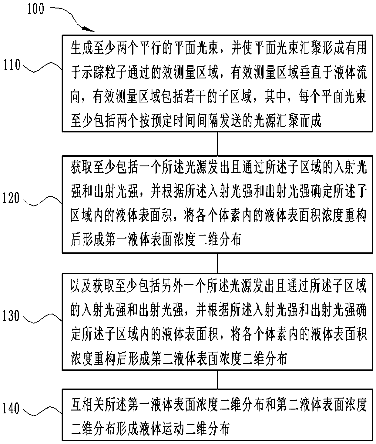
[0046] Such as figure 1 As shown, the flow velocity measurement method 100 provided by the present application includes the following steps:

[0047] Step 110: Generate at least two parallel planar light beams, and make the planar light beams converge to form an effective measurement area 230 for the passage of tracer particles. The effective measurement area 230 is divided into several sub-areas, and each planar light beam At least two light sources sent at predetermined time intervals...


PUM


Abstract

The invention relates to a flowing speed measurement method. The method comprises the steps: at least two parallel plane light beams are generated, the plane light beams are converged to form an effective measurement area for tracer particles to pass through, the effective measurement area is divided into a plurality of subareas, and each plane light beam is formed by converging at least two lightsources sent according to a preset time interval; incident light intensity and emergent light intensity which are emitted by the light sources and pass through the subareas are acquired respectively,and a first distribution image and a second distribution image of the tracer particles are formed according to attenuation of the incident light intensity and the emergent light intensity; cross-correlating of the first distribution image and the second distribution image is carried out to form a flow distribution of the tracer particles. According to the flowing speed measuring method and system, the mutual shielding phenomenon of particles can be avoided, the light intensity distribution, the background noise of the measured area and the like do not influence the speed measuring result, andthe influence of soot can be avoided by selecting the proper wavelength.

Description

technical field [0001] The application belongs to the field of imaging technology, in particular to a method and system for measuring the velocity of flowing particles. Background technique [0002] Particle Image Velocimetry (PIV) traditionally uses high-energy short-wavelength pulsed YAG (Yttrium Aluminum Garnet, yttrium aluminum garnet) laser (wavelength about 532nm) by tomography. [0003] However, the traditional chromatographic PIV method has the following disadvantages: [0004] 1) Single pulse laser energy is generally greater than 30mJ, and high-energy short-wavelength lasers are more harmful to human eyes; [0005] 2) Most of the traditional tomographic PIV methods use dispersion technology. If multiple tracer particles overlap on a certain tomographic calculation plane at the same detection angle, different particles may not be able to be distinguished due to a certain probability of mutual shadowing; [0006] 3) The three-dimensional space size of the tradition...

Claims


Application Information

Patent Timeline
Patent Type & Authority Applications(China)
IPC IPC(8): G01P5/20G01P5/26
CPCG01P5/20G01P5/26
Inventor 胡文成张宝华李孝堂范玮
Owner AECC SHENYANG ENGINE RES INST
Why Eureka
Try Eureka