Device with digital phase-locked loop and numerical control oscillator and method for measuring phase noise and amplitude noise

A numerically controlled oscillator and digital phase-locked loop technology, which is applied in measurement devices, noise figure or signal-to-noise ratio measurement, measurement of electricity and other directions, can solve the problems of phase noise spectrum power attenuation, etc. The effect of high ratio and high measurement accuracy

Active Publication Date: 2020-04-17
SOUTHEAST UNIV
View PDF5 Cites 1 Cited by
  • Summary
  • Abstract
  • Description
  • Claims
  • Application Information

AI Technical Summary

Problems solved by technology

[0004] In order to solve the above problems, the present invention discloses a device for measuring phase noise and amplitude noise with a digital phase-locked loop and a numerically c

Method used


Image

  • Device with digital phase-locked loop and numerical control oscillator and method for measuring phase noise and amplitude noise
  • Device with digital phase-locked loop and numerical control oscillator and method for measuring phase noise and amplitude noise
  • Device with digital phase-locked loop and numerical control oscillator and method for measuring phase noise and amplitude noise

Examples


Embodiment 2

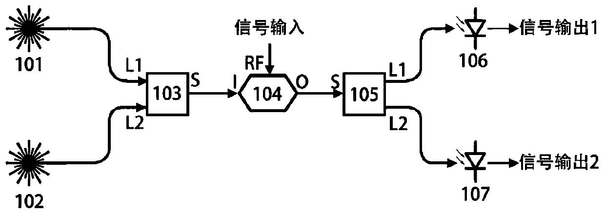
[0047] On the basis of Embodiment 1, this example provides a feasible structure of the power division unit in the device for measuring phase noise and amplitude noise with a digital phase-locked loop and a numerically controlled oscillator, that is, a WDM modulation method Optical isolation structure. Such as figure 2 As shown, the power division unit includes a first laser 101 , a second laser 102 , a multiplexer 103 , a first optical modulator 104 , a splitter 105 , a first optical detector 106 , and a second optical detector 107 . The first laser 101 and the second laser 102 generate laser light with different wavelengths, which respectively enter the L1 port and the L2 port of the multiplexer 103 . The S port output signal of the multiplexer 103 is connected to the I port of the first optical modulator 104 . The signal to be tested 1 is connected to the RF port of the first optical modulator 104 to modulate the signal to be tested onto light. The O port output of the f...

Embodiment 3

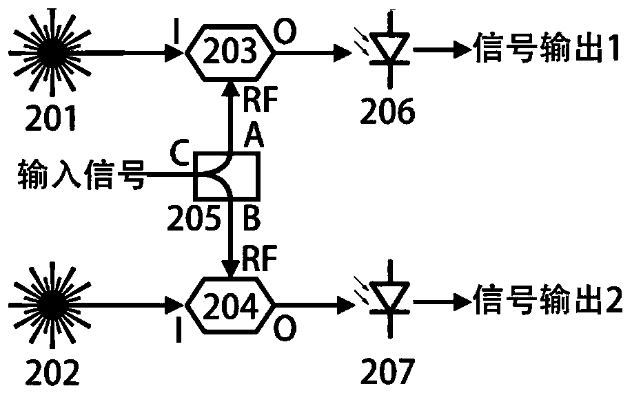
[0049] On the basis of Embodiment 1, this example provides another feasible structure of the power division unit in the device for measuring phase noise and amplitude noise with a digital phase-locked loop and a numerically controlled oscillator, that is, a light wave separately modulated isolation structure. Such as image 3 As shown, the power division unit includes a third laser 201, a fourth laser 202, a second optical modulator 203, a third optical modulator 204, an electric power divider 205, a third optical detector 206, and a fourth optical detector 207 . The third laser 201 sends light into the I port of the second light modulator 203 , and the fourth laser 202 sends light into the I port of the third light modulator 204 . The signal 1 to be tested is connected to the C port of the electric power divider 205, and the signal is divided into two paths, which are respectively output through the A port and the B port, and are respectively connected to the RF port of the...

Embodiment 4

[0051] On the basis of the first to third embodiments, this example provides a feasible mode of the amplitude-phase demodulation unit in the device for measuring phase noise and amplitude noise with a digital phase-locked loop and a numerically controlled oscillator. Both the first phase demodulation unit 22 and the second phase demodulation unit 31 can adopt this structure, as Figure 4 As shown, it specifically includes: a signal phase shifting and distribution unit 401, a first amplitude-phase demodulation mixer 402, a first demodulation filter 403, an amplitude-phase calculation unit 404, and a second amplitude-phase demodulation mixer 405 , the second demodulation filter 406 .

[0052] The digital intermediate frequency signal to be tested is sent to the R port of the first amplitude-phase demodulation mixer 402 and the R port of the second amplitude-phase demodulation mixer 405 . The reference signal is sent into the IN port of the signal phase-shifting and distribution...


PUM


Abstract

The invention discloses a device with a digital phase-locked loop and a numerical control oscillator for measuring phase noise and amplitude noise and an implementation method of the device. The device comprises a power dividing unit, two analog down-conversion and digitization subsystems, two digital phase-locked demodulation subsystems and a data processing unit. Signals to be measured are divided into two paths to be mixed with analog local oscillator signals respectively, and digital intermediate frequency signals are sent to the digital phase-locked demodulation subsystem after filtering,amplification and analog-to-digital conversion. The digital intermediate frequency signal is divided into two paths: one path is input into the digital phase-locked loop, so the tracking numerical control oscillator and the digital intermediate frequency signal are phase-locked, and the frequency control unit tracks the frequency of the numerical control oscillator, calculates a reference frequency and controls the numerical control oscillator to output a digital sinusoidal signal of which the frequency and phase are the reference frequency and phase; and the other path of signal is delayed and then mixed with an output signal of the numerical control oscillator, and then is sent to a digital processing unit after amplitude-phase demodulation and filtering to obtain a phase noise spectrumand an amplitude noise spectrum through cross-correlation calculation. The method is small in attenuation and high in precision.

Description

technical field [0001] The invention belongs to the field of optoelectronics and microwave technology, and relates to a device and method for measuring phase noise and amplitude noise with a digital phase-locked loop and a numerically controlled oscillator. Background technique [0002] Low phase noise and amplitude noise signal sources are of great significance to radar and communication. Driven by a low noise source, the radar can obtain a high signal-to-noise ratio, and thus high sensitivity. In communications, low phase noise sources can achieve high signal-to-noise ratios, increasing bandwidth capacity. But the lower the phase noise of the signal source, the more difficult it is to measure. Therefore, it is very important to improve the accuracy of measuring phase noise. [0003] The current phase noise measurement schemes include: direct spectrum measurement method, analog delay line frequency discrimination method, digital delay line frequency discrimination method...

Claims


Application Information

Patent Timeline
IPC IPC(8): H03L7/099H03L7/091H03L7/093H03L7/16G01R29/26G01R1/30
CPCH03L7/0991H03L7/091H03L7/093H03L7/16G01R29/26G01R1/30
Inventor 王子晔杨春朱恩徐玮杰
Owner SOUTHEAST UNIV
Why Eureka
Try Eureka