
Workpiece surface shape measuring system and method

A measurement system and measurement method technology, applied in the field of workpiece surface shape measurement system, can solve the problems of laser interference, easy to scratch the surface of components, low measurement efficiency, etc. The effect of detection time

Inactive Publication Date: 2018-05-15
CHANGCHUN INST OF OPTICS FINE MECHANICS & PHYSICS CHINESE ACAD OF SCI
View PDF7 Cites 3 Cited by
  • Summary
  • Abstract
  • Description
  • Claims
  • Application Information

AI Technical Summary

Problems solved by technology

[0003] The in-situ detection system equipped with a single-point diamond lathe is mainly a contact ball probe, which has poor accuracy, low measurement efficiency, and is easy to scratch the surface of the component
At the same time, the surface of the aluminum alloy reflector is very soft, and the pressure of the measuring head causes the mirror to deform elastically, thus introducing measurement errors
Chinese patent CN205580399U proposes a measurement method of laser three-dimensional scanning. Although this method can realize non-contact measurement, the presence of impurities such as oil on the ultra-precision turning surface will interfere with the laser, and the scattering of the laser on the reflective mirror will also introduce measurement errors.
Chinese patent CN102305601A proposes a method of using a grating projection device to project sinusoidal grating fringes on the surface of the measured object, and the image acquisition device obtains the deformed fringe pattern modulated by the surface of the measured object, and then restores the method of the three-dimensional shape of the surface of the measured object, but this The resolution of the method is not high, and it is only suitable for the measurement of surface errors above the micron level

Method used

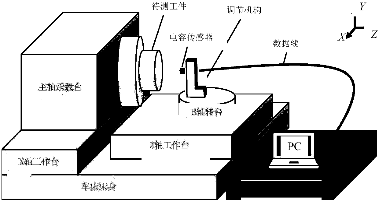
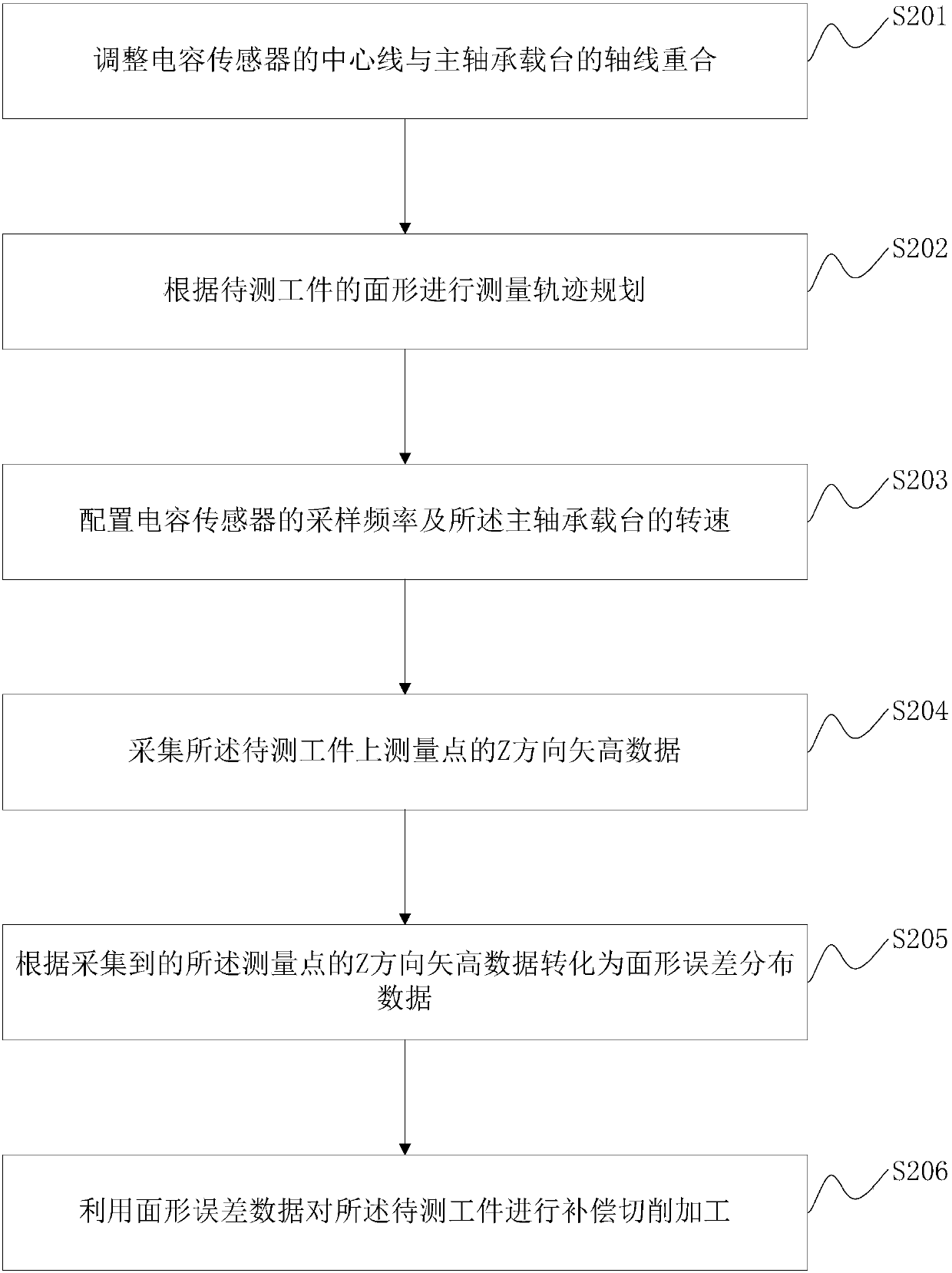
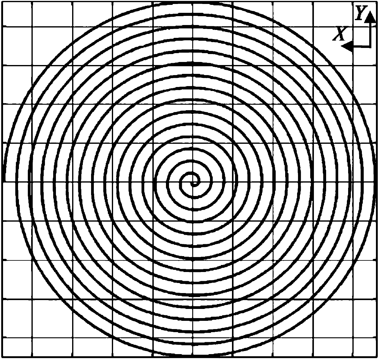

Image

  • Workpiece surface shape measuring system and method
  • Workpiece surface shape measuring system and method
  • Workpiece surface shape measuring system and method

Examples


Embodiment Construction

[0032] In order to enable those skilled in the art to better understand the solutions of the present invention, the following will clearly and completely describe the technical solutions in the embodiments of the present invention in conjunction with the drawings in the embodiments of the present invention. Obviously, the described embodiments are only It is an embodiment of a part of the present invention, but not all embodiments. Based on the embodiments of the present invention, all other embodiments obtained by persons of ordinary skill in the art without making creative efforts shall fall within the protection scope of the present invention.

[0033] The terms "first", "second", "third", "fourth", etc. (if any) in the description and claims of the present invention and the above drawings are used to distinguish similar objects, and not necessarily Used to describe a specific sequence or sequence. It is to be understood that the terms so used are interchangeable under app...


PUM


Abstract

The embodiment of the invention provides a workpiece surface shape measuring system and a workpiece surface shape measuring method. According to the invention, the measuring stability of a capacitivesensor is high. Meanwhile, the complex linear correction of data is not required white the linear measurement can be well achieved. Moreover, surface oil contamination and other impurities do not influence the capacitive sensor, so that the measurement result of the capacitive sensor cannot be influenced. Meanwhile, the working surface of the capacitive sensor is a circular region and has a certain sampling area. Therefore, local large deviation errors in a primary sampling area can be homogenized. As a result, the accidental high point of the measurement result of the capacitive sensor is reduced and a reasonable surface shape peak valley value is obtained. The surface shape error measurement is greatly facilitated.

Description

technical field [0001] The invention relates to the technical field of advanced manufacturing of space optical systems, in particular to a workpiece surface shape measurement system and method. Background technique [0002] Ultra-precision turning is a high-efficiency optical component processing method, which can simultaneously obtain nanometer surface roughness and submicron surface shape accuracy. Generally speaking, the optical components after ultra-precision turning can directly meet the requirements for the use of infrared band components. However, ultra-precision turning optical components cannot meet the surface shape requirements of optical components in the visible light band. Especially for mirrors with large diameter or large diameter-to-thickness ratio, large surface shape errors will be introduced due to factors such as machine tool guideway errors, thermal deformation during processing, and clamping stress. [0003] The in-situ detection system equipped wit...

Claims


Application Information

Patent Timeline
Patent Type & Authority Applications(China)
IPC IPC(8): G05B19/19G01B7/28
CPCG05B19/19G01B7/281G05B2219/37272G05B2219/37365G05B2219/37457
Inventor 张志宇李兴昶熊玲罗霄李锐钢薛栋林张学军
Owner CHANGCHUN INST OF OPTICS FINE MECHANICS & PHYSICS CHINESE ACAD OF SCI
Learn More