Steel channel punching device

A punching device and punching technology, applied in the field of mechanical processing, can solve problems such as the accumulation of punching and blanking, and achieve the effects of low cost, avoiding secondary cleaning, and high processing efficiency

Pending Publication Date: 2020-03-17
山东三森数控机械有限公司
View PDF0 Cites 1 Cited by
  • Summary
  • Abstract
  • Description
  • Claims
  • Application Information

AI Technical Summary

Problems solved by technology

[0002] When the existing channel steel punching processing equipment punches the channel steel, it is often necessary to punch the three sides of the channel steel. Due to the limitation of the processing space, the opening of the channel steel generally faces upward when the channel steel is positioned. , resulting in the accumulation of punching and blanking in the channel steel. In the process of channel steel processing, because the channel steel is gradually pushed forward by the pushing trolley, the remaining material accumulated in the channel steel is due to the punching and falling. Due to the uncertainty of the direction, in order to ensure that the punching and blanking will not affect the punching process on the bottom surface, it is necessary to add a cleaning mechanism to clean the blanking in time

Method used


Image

  • Steel channel punching device
  • Steel channel punching device
  • Steel channel punching device

Examples


Embodiment Construction

[0019] In order to clearly illustrate the technical features of the solution of the present invention, the solution will be further elaborated below in conjunction with the accompanying drawings and through specific implementation methods.

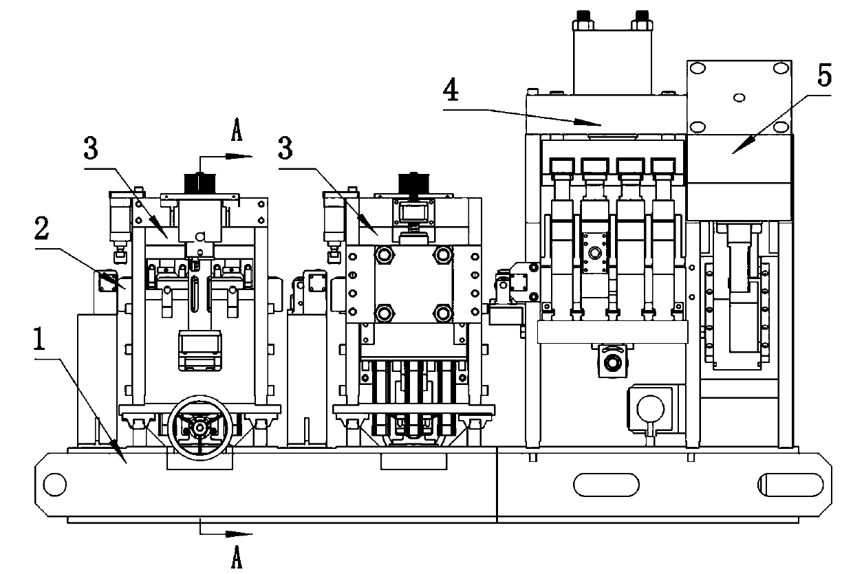
[0020] Such as figure 1 As shown in , a new channel steel punching device changes the traditional channel steel positioning method to open downward, so that the blanking produced in the channel steel punching can fall naturally by the gravity of the blanking Under the workpiece and can be conveniently collected.

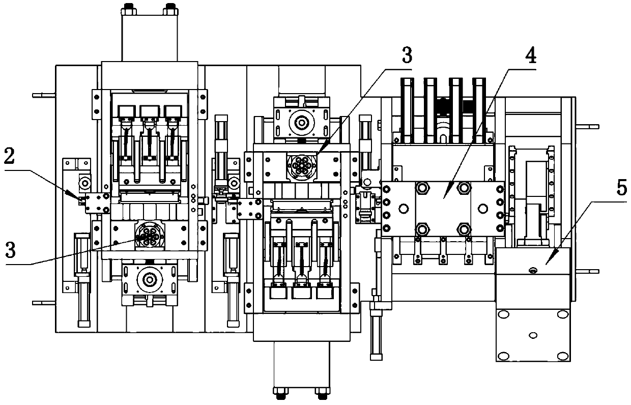
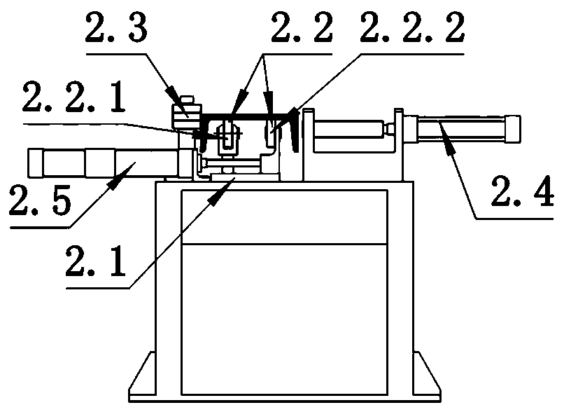
[0021] The present invention is achieved through the following technical solutions. A channel steel punching device is provided, including a fuselage 1, a supporting mechanism 2, a side punching unit 3, a bottom punching unit 4 and a cutting unit 5. The bottom punching After the hole unit is placed on the side punching unit, the installation direction of the channel steel lifted by the supporting mechanism 2 is that the opening ...


PUM


Abstract

The invention relates to a steel channel punching device. The steel channel punching device comprises a machine body, a material supporting mechanism, two side face punching units, a bottom surface punching unit and a cutoff unit. The bottom surface punching unit is arranged behind the side face punching units. A steel channel supported by the material supporting mechanism is provided with a downward opening. The two side face punching units are arranged in bilateral symmetry in a front-back staggered mode. Each side face punching unit comprises a punch die frame, a transmission lead screw anda punching cylinder, wherein the transmission lead screw and the punching cylinder are driven by a servo motor; the transmission lead screw is fixedly connected relative to the machine body; the punch die frame is fixedly connected with one end of the transmission lead screw; the punch die frame is provided with a U-shaped transition part; one side of the U-shaped transition part is provided witha punching female die, and the other side of the U-shaped transition part is provided with a through hole; and a pressure head of the punching cylinder penetrates through the through hole to be fixedly provided with a punch pin. Through change of the mounting direction of the steel channel and redesign of a side face punching mechanism, the steel channel punching device realizes internal punchingmachining in a confined space and has the beneficial effects of high machining efficiency and low cost.

Description

technical field [0001] The invention relates to the technical field of mechanical processing, in particular to a punching device, in particular to a channel steel punching device. Background technique [0002] When the existing channel steel punching processing equipment punches the channel steel, it is often necessary to punch the three sides of the channel steel. Due to the limitation of the processing space, the opening of the channel steel generally faces upward when the channel steel is positioned. , resulting in the accumulation of punching and blanking in the channel steel. In the process of channel steel processing, because the channel steel is gradually pushed forward by the pushing trolley, the remaining material accumulated in the channel steel is due to the punching and falling. Due to the uncertainty of the direction, in order to ensure that the punching and blanking will not affect the punching process on the bottom surface, it is necessary to add a cleaning me...

Claims


Application Information

Patent Timeline
Patent Type & Authority Applications(China)
IPC IPC(8): B21D28/24B21D43/00
CPCB21D28/243B21D43/003
Inventor 任云章罗洪波李光磊周恭泉
Owner 山东三森数控机械有限公司
Why Eureka
Try Eureka