Hydraulic rotary machining table for automobile metal part machining center

A machining center, hydraulic rotation technology, applied in the direction of workbench, manufacturing tools, etc., can solve the problems of cumbersome processing, difficult to control the precision of parts, low processing efficiency, etc., to improve processing efficiency, avoid multiple clamping, improve processing The effect of precision and productivity

Inactive Publication Date: 2018-12-07
ANHUI TIANYU AUTO PARTS MFG
View PDF7 Cites 1 Cited by
  • Summary
  • Abstract
  • Description
  • Claims
  • Application Information

AI Technical Summary

Problems solved by technology

[0004] Aiming at the deficiencies of the prior art, the present invention provides a hydraulic rotary processing table for the machining center of automobile metal parts, which solves the problem that due to the irregular shape of some metal parts, the processing is relatively cumbersome and requires multiple clamping and changing processes. position, resulting in the difficulty of controlling the accuracy of the final part, and the problem of low processing efficiency

Method used


Image

  • Hydraulic rotary machining table for automobile metal part machining center
  • Hydraulic rotary machining table for automobile metal part machining center
  • Hydraulic rotary machining table for automobile metal part machining center

Examples


Embodiment Construction

[0027] The following will clearly and completely describe the technical solutions in the embodiments of the present invention with reference to the accompanying drawings in the embodiments of the present invention. Obviously, the described embodiments are only some, not all, embodiments of the present invention. Based on the embodiments of the present invention, all other embodiments obtained by persons of ordinary skill in the art without making creative efforts belong to the protection scope of the present invention.

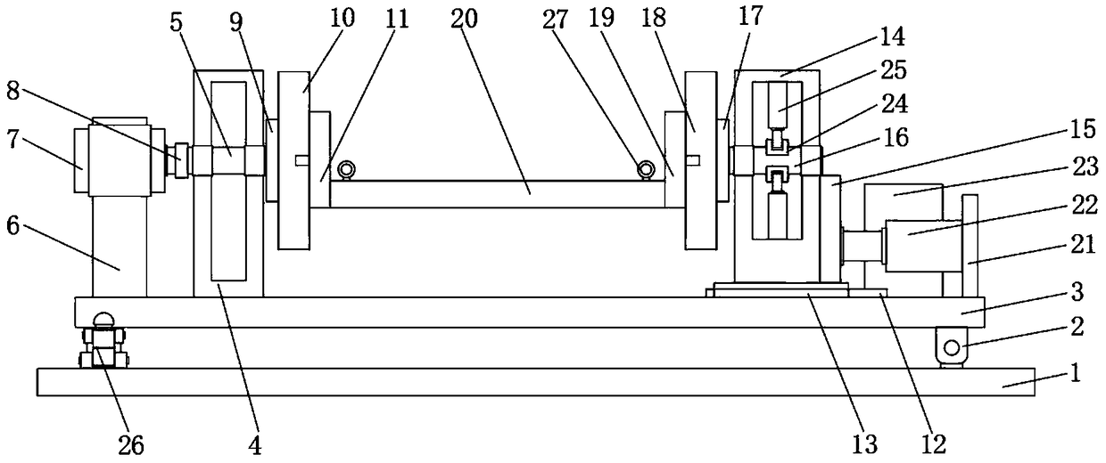
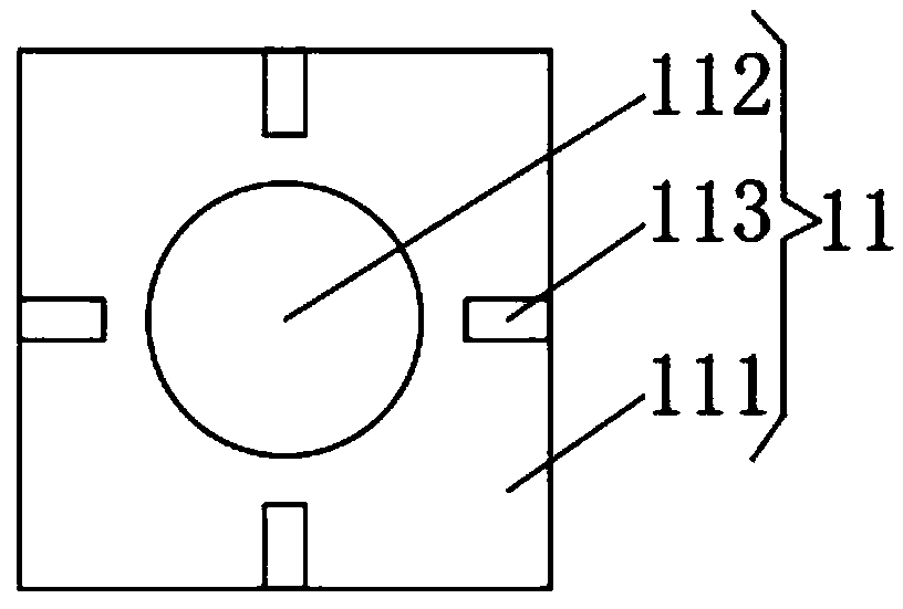
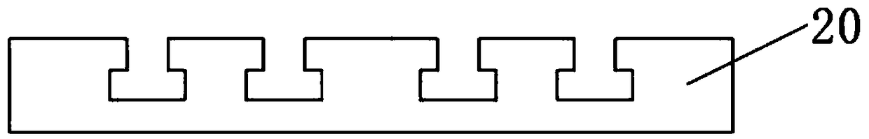
[0028] see Figure 1-5 , the present invention provides a technical solution: a hydraulic rotary processing table of an automobile metal parts machining center, including a mounting base plate 1, the top side of the mounting base plate 1 is connected with a fixed base plate 3 through a rotating part 2, and the top of the fixed base plate 3 is a The side is fixedly connected with a first box body 4, the inner wall of the first box body 4 is rotatably connected ...


PUM


Abstract

The invention discloses a hydraulic rotary machining table for an automobile metal part machining center. The hydraulic rotary machining table comprises a mounting bottom plate, one side of the top ofthe mounting bottom plate is connected with a fixing bottom plate in a rotating mode through a rotating piece, one side of the top of the fixing bottom plate is fixedly connected with a first box body, the inner wall of the first box body is connected with a first rotating shaft in a rotating mode, the top of the fixing bottom plate is fixedly connected with a rotating oil cylinder through a fixing frame, the side, far away from the first box body, of the top of the fixing bottom plate is fixedly connected with a sliding track, a sliding base is connected with the surface of the sliding trackin a sliding mode, the top of the sliding base is sequentially and fixedly connected with a second box body and a push plate, and the inner wall of the second box body is connected with a second rotating shaft in a rotating mode. The invention relates to the technical field of automobile machining equipment. According to the hydraulic rotary machining table for the automobile metal part machiningcenter, problems that final precision of the parts is difficult to control due to the fact that the appearances of some metal parts are in irregular shapes, thus machining process is complicated andrepeated clamping and changing machining positions are required to be carried out, and machining efficiency is low are solved.

Description

technical field [0001] The invention relates to the technical field of automobile processing equipment, in particular to a hydraulic rotary processing table of an automobile metal parts processing center. Background technique [0002] Auto parts are the various units that make up the whole car and a product that serves the car. There are many kinds of auto parts. With the improvement of people's living standards, people consume more and more cars, and the market for auto parts is getting bigger and bigger. In recent years, auto parts manufacturers are also developing rapidly. Some auto parts are metal parts and need to be processed in the machining center. However, due to the irregular shape of some metal parts, the processing is more cumbersome and requires multiple assembly. The clip changes the processing position, which makes it difficult to control the accuracy of the final part, and the processing efficiency is low. Contents of the invention [0003] (1) Solved tec...

Claims


Application Information

Patent Timeline
Patent Type & Authority Applications(China)
IPC IPC(8): B25H1/18B25H1/10
CPCB25H1/10B25H1/18
Inventor 李支峰
Owner ANHUI TIANYU AUTO PARTS MFG
Why Eureka
Try Eureka