A multifunctional five-axis manipulator workstation

A mechanical arm and multi-functional technology, applied in the field of robotics, can solve the problems of low control precision and low degree of freedom of the end effector, achieve the effect of flexible and comprehensive printing work, reduce secondary processing, and improve efficiency

Active Publication Date: 2020-03-10
达州市天宝锦湖电子有限公司
View PDF6 Cites 0 Cited by
  • Summary
  • Abstract
  • Description
  • Claims
  • Application Information

AI Technical Summary

Problems solved by technology

[0004] The technical problem to be solved by the present invention is to provide a multi-functional five-axis manipulator workstation to solve the problem in the prior art that the control precision of the end effector is not high during the movement of the manipulator with less degrees of freedom

Method used


Image

  • A multifunctional five-axis manipulator workstation
  • A multifunctional five-axis manipulator workstation
  • A multifunctional five-axis manipulator workstation

Examples


Embodiment 1

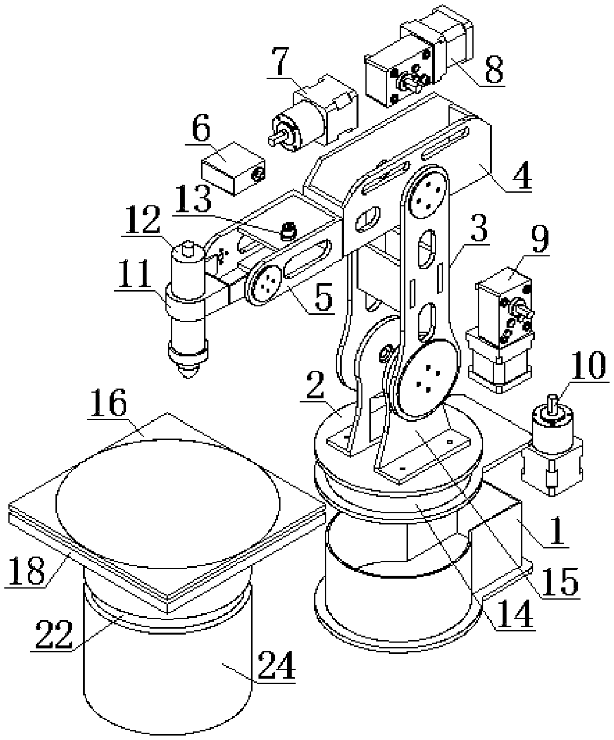
[0034] A multifunctional five-axis robotic arm workstation, such as Figure 1 to Figure 5 As shown, it includes a base 1, a rotary table 2, a rear arm 3, an intermediate arm 4, a forearm 5, and an end effector 12. A second planetary gear reducer 10 is fixedly connected in the base 1. Between the rotary table 2 and the base 1 A thrust ball bearing 14 is installed, the output shaft of the second planetary gear reducer 10 is fixedly connected with the turntable 2 through the flange, and a bracket 15 is fixedly connected to the top of the turntable 2, and the second planetary gear reducer 10 drives the bracket 15 Turn horizontally on base 1. The second worm gear reducer 9 is fixedly connected in the bracket 15, and the bottom of the rear arm 3 is fixedly connected with the output shaft of the second worm gear reducer 9 through a flange, so that the rear arm can rotate vertically on the bracket 15. The middle arm 4 is fixedly connected with the first worm gear reducer 8 and the fi...

Embodiment 2

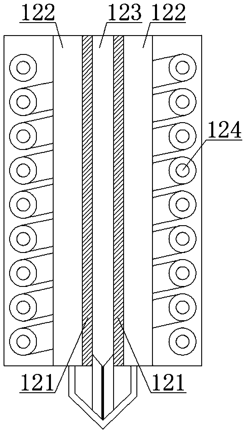
[0038] This embodiment is further improved on the basis of the above embodiments, such as figure 2 As shown, when the end effector 12 is a metal print head, a graphite tube 121 is provided outside the material tube 123 in the metal print head, a shielding gas channel 122 is provided on the outside of the graphite tube 121, and a shielding gas channel 122 is wound on the outside of the shielding gas channel 122. The induction coil 124 is driven by an external ZVS switch circuit. The circuit diagram of the ZVS switch circuit is shown in Figure 5 As shown in the figure, L1 and L2 are respectively connected to the induction coil 124, the induction coil is made of copper wire, and ±48V is connected to the power supply, and the high-efficiency intermediate frequency induction inverter is realized through the ZVS switching circuit, and the graphite tube 121 passes through its own The induced current generates Joule heat, which melts the material quickly, and the liquid metal is ex...

Embodiment 3

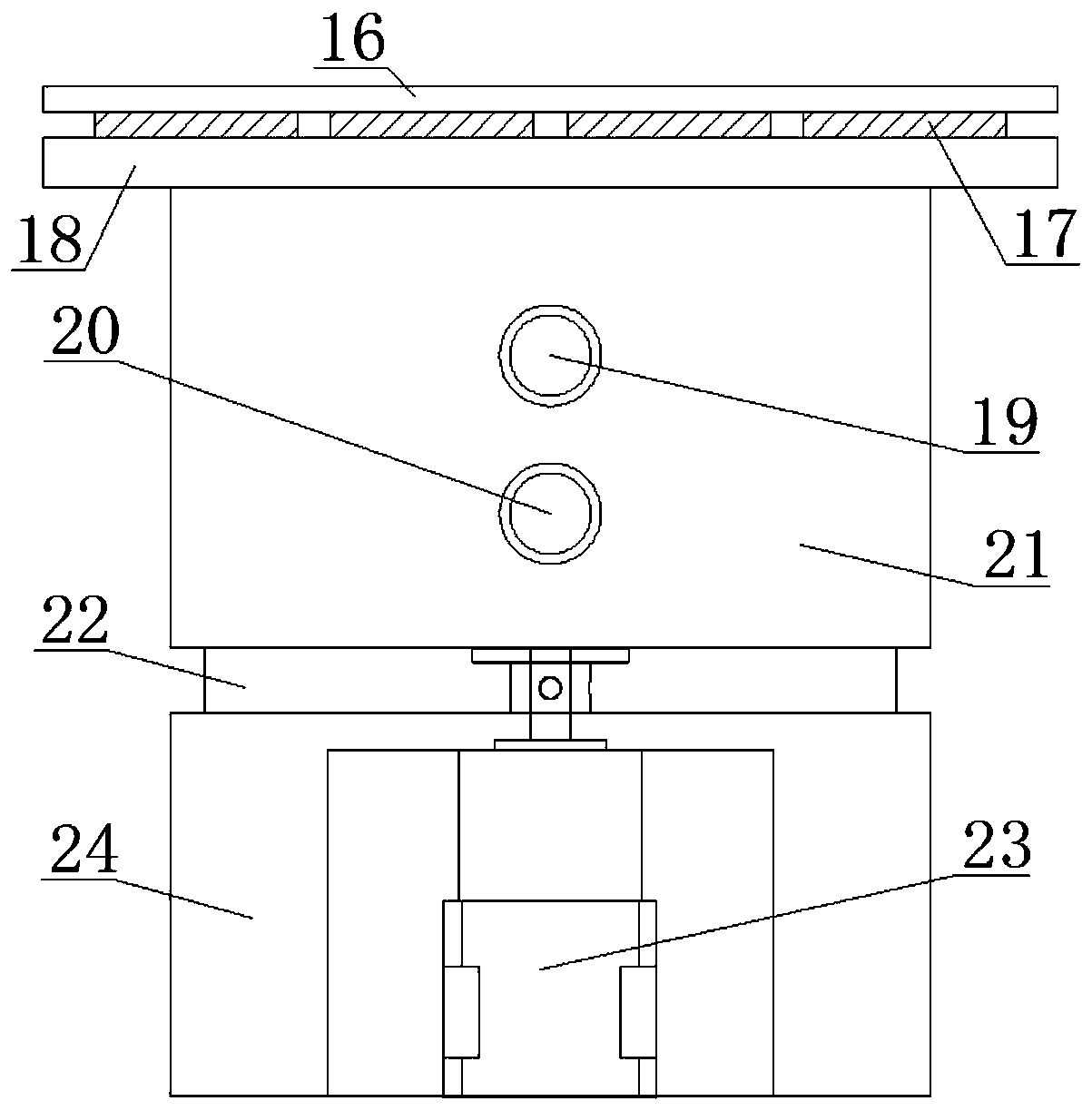
[0040] This embodiment is further improved on the basis of the above embodiments, such as image 3 , Figure 4 As shown, a water cooling device is provided below the metal print head, and the water cooling device includes a semiconductor cooling chip 17, a water cooling tank 21 and a copper tube 25. The top of the semiconductor cooling chip 17 is provided with a heat absorbing platform 16, and the bottom of the semiconductor cooling chip 17 is provided with The heat-absorbing bottom plate 18 and the side wall of the water-cooling tank 21 are provided with a water inlet 19 and a water outlet 20 respectively. , The water outlet 20 is sealed and connected. A water-cooling base 24 is also provided below the water-cooling tank 21, and a third planetary gear reducer 23 is fixedly connected in the water-cooling base 24. A b thrust ball bearing 22 is installed between the water-cooling tank 21 and the water-cooling base 24, and the third planetary gear The output shaft of the speed ...


PUM


Abstract

The invention relates to a multifunctional five-axis mechanical arm working station. The multifunctional five-axis mechanical arm working station comprises a base, a rotating table, a back arm, a middle arm, a front arm and a terminal actuator; a second planet gear speed reducer is fixedly connected into the base; an output shaft of the second planet gear speed reducer is fixedly connected with the rotating table through a flange; the bottom of the back arm is fixedly connected with an output shaft of a second turbine worm speed reducer through a flange; the top of the back arm is fixedly connected with an output shaft of a first turbine worm speed reducer through a flange; the front arm is fixedly connected with an output shaft of a first planet gear speed reducer through a flange; a free end of the front arm is fixedly connected with a servo steering engine; and the servo steering engine is connected with a fixture. A mechanical arm has five degrees of freedom, so that the printing work is more flexible and comprehensive; and secondary machining is reduced in the side surface machining of printed objects, so that the working efficiency of 3D printing is improved. Output shafts of all motors are directly acted on the base, the back arm, the middle arm, the front arm and the terminal actuator to improve the printing precision.

Description

technical field [0001] The invention relates to the technical field of robots, in particular to a multifunctional five-axis manipulator workstation. Background technique [0002] The robotic arm technology of the robot in the prior art is a high-tech formed by integrating various disciplines such as mechanism, informatics, sensing technology and automatic control. With the wide application of robotic arms in life and industry, robotic arms The design of the solution has been continuously improved and innovated to continuously improve the performance of control accuracy, stability and production efficiency. According to different applications, the design of the robot arm is also varied, especially the application of the robot arm in 3D printing technology. Among them, the FDM fused deposition modeling process is a commonly used 3D printing technology manufacturing process at present. Its materials are generally fed in filaments. The materials are heated and melted in the nozz...

Claims


Application Information

Patent Timeline
Patent Type & Authority Patents(China)
IPC IPC(8): B25J9/00B25J19/00
CPCB25J9/00B25J19/00
Inventor 门正兴王子强何智林唐鑫郭庆丰
Owner 达州市天宝锦湖电子有限公司
Why Eureka
Try Eureka