Cutting equipment for foam sheet and working method of cutting equipment

A foam and equipment technology, applied in the field of foam sheet cutting equipment, can solve the problems of reduced cutting accuracy, affecting cutting efficiency, cutting errors, etc., and achieve the effect of preventing offset and ensuring accuracy

Pending Publication Date: 2020-03-17
沃时派客(上海)包装科技有限公司
View PDF6 Cites 2 Cited by
  • Summary
  • Abstract
  • Description
  • Claims
  • Application Information

AI Technical Summary

Problems solved by technology

[0004] The object of the present invention is to provide a kind of cutting equipment and working method for foam sheet, can solve existing this kind of equipment and still have certain defect when using, firstly because a large amount of foam chips will be produced in the cutting process If it is not cleaned in time, it will not only affect the cutting efficiency, but also easily lead to a decrease in cutting accuracy, and the existing cutting equipment often adjusts the cutting direction by adjusting the direction of the slice during the cutting process. This method is extremely It is easy to cause cutting errors due to errors caused by excessive slice adjustments, and there is a lack of components to limit the slice direction. In the process of curve cutting, it is necessary to continuously adjust the direction and position of slices and foam sheets, which is extremely troublesome

Method used


Image

  • Cutting equipment for foam sheet and working method of cutting equipment
  • Cutting equipment for foam sheet and working method of cutting equipment
  • Cutting equipment for foam sheet and working method of cutting equipment

Examples


Embodiment Construction

[0033] The technical solutions of the present invention will be clearly and completely described below in conjunction with the embodiments. Apparently, the described embodiments are only some of the embodiments of the present invention, not all of them. Based on the embodiments of the present invention, all other embodiments obtained by persons of ordinary skill in the art without creative efforts fall within the protection scope of the present invention.

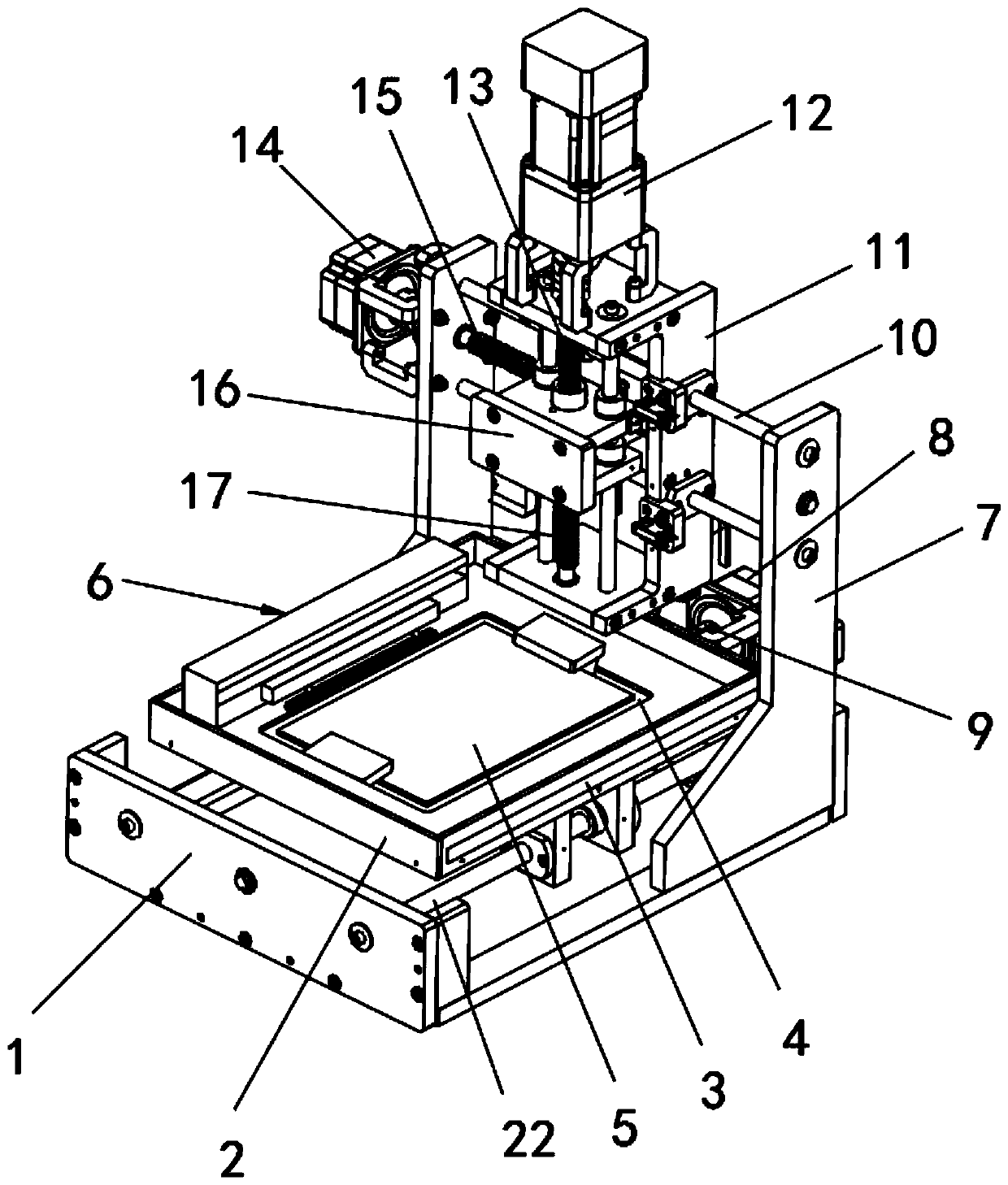
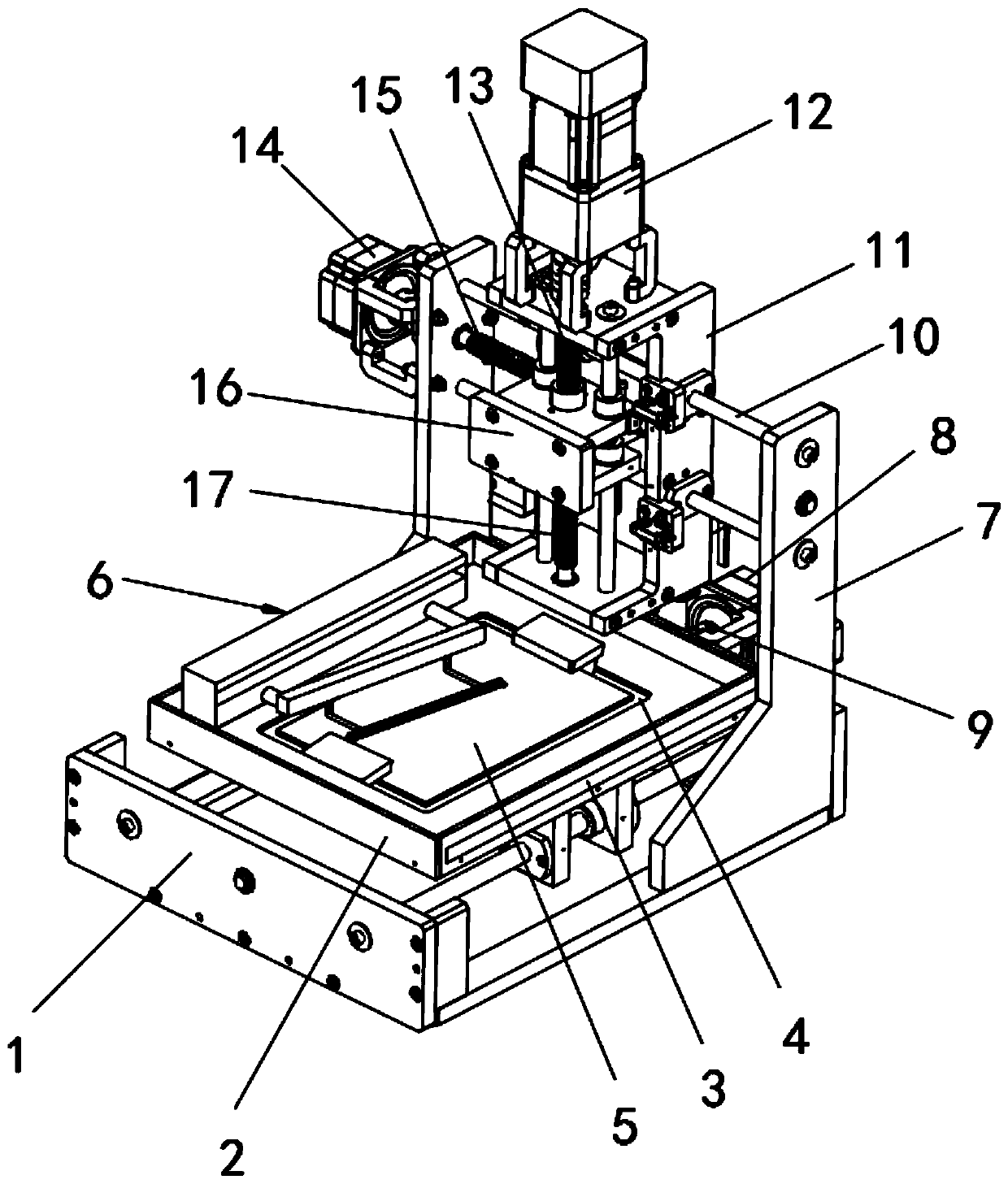
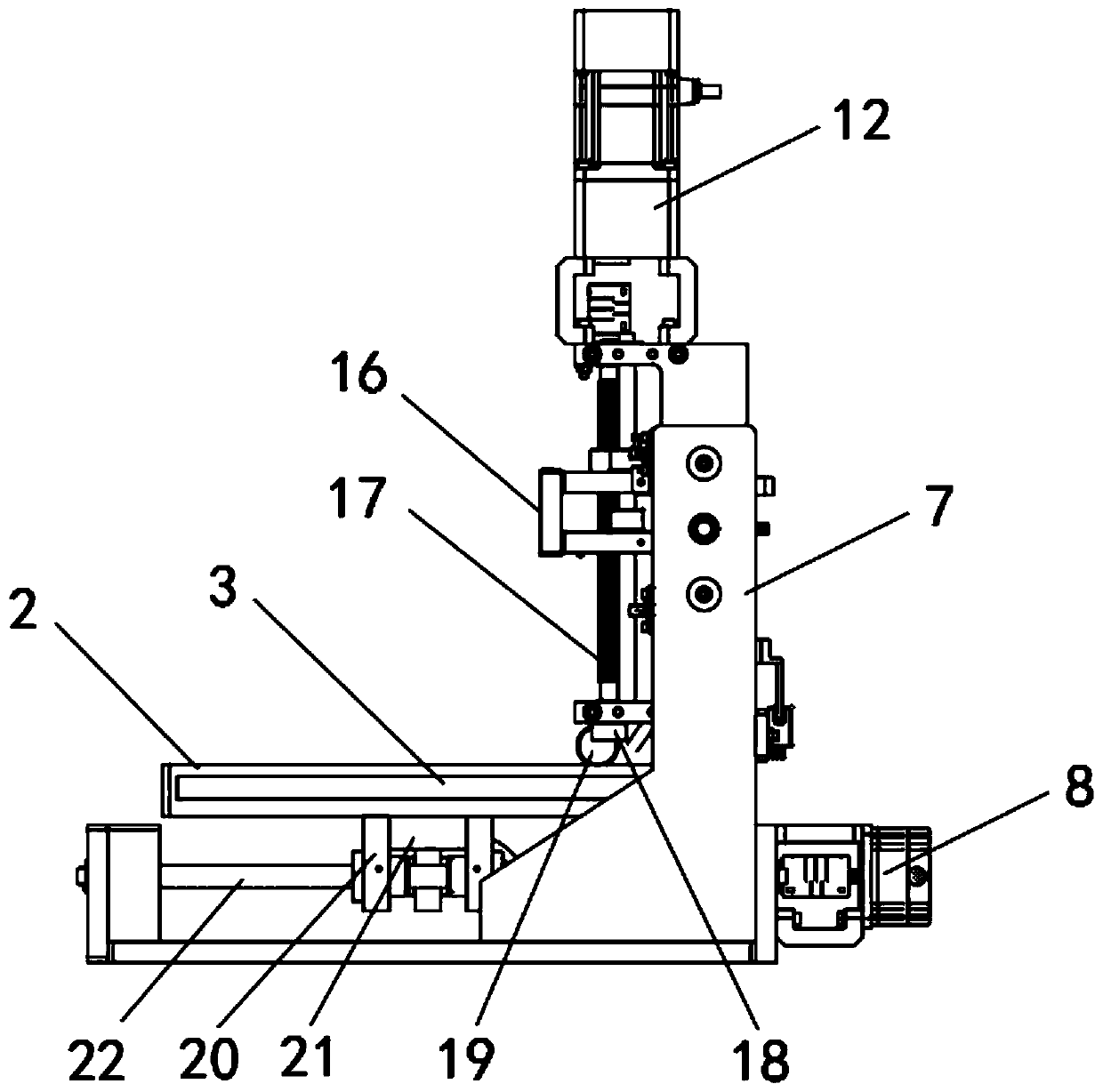
[0034] see Figure 1-7 As shown, a cutting device for foam sheets includes a base 1, a movable seat 2, a cutter positioning mechanism 6, a bracket 7 and a movable frame 11, and the base 1 is provided with two guide rails 22, two guide rails 22 A slide plate 20 is connected between them, a suction fan 21 is fixedly installed in the middle of the slide plate 20, a movable seat 2 is fixedly installed on the top of the slide plate 20, a bottom hydraulic cylinder 8 is fixedly installed on the base 1, and a bottom hydraulic cylin...


PUM


Abstract

The invention discloses cutting equipment for a foam sheet, and the equipment comprises a base, a movable seat, a cutter trend positioning mechanism, a support and a movable frame; two guide rails arearranged on the base, and a sliding plate is jointly connected between the two guide rails in a penetrating mode. The problem that the existing equipment still has certain defects during use can be solved: a large number of foam scraps are generated in the cutting process, and is not cleared timely, which affects the cutting efficiency, and is liable to cause the reduction of the cutting accuracy; the cutting direction of the existing cutting equipment is often adjusted by adjusting the direction of a slice in the cutting process, which enables the situation that cutting errors are caused byerrors due to the fact that the slice adjusting amplitude is too large to be extremely likely to happen; components for limiting the slice trend are lacked; meanwhile, in the oblique line or curve cutting process of existing equipment, direction and position adjustment needs to be continuously conducted on slices and foam sheets, which is very troublesome.

Description

technical field [0001] The invention relates to the field of foam sheet cutting equipment, in particular to a foam sheet cutting equipment and a working method thereof. Background technique [0002] Foam sheets need to use specific cutting equipment during the cutting process. However, there are still some defects in the existing equipment. , not only affects the cutting efficiency, but also easily leads to a decrease in cutting accuracy, and the existing cutting equipment often adjusts the cutting direction by adjusting the direction of the slice during the cutting process. The adjustment range is too large and errors lead to cutting errors, and there is a lack of components to limit the direction of the slice. At the same time, the existing equipment is extremely convenient for straight line cutting, but it is difficult to perform oblique or curved cutting. In the process, it is necessary to continuously adjust the direction and position of the slices and foam sheets, whi...

Claims


Application Information

Patent Timeline
Patent Type & Authority Applications(China)
IPC IPC(8): B26D1/18B26D7/18B26D7/26B26D7/00
CPCB26D1/185B26D7/1863B26D7/2635B26D7/00B26D2007/0012
Inventor 黄昌海
Owner 沃时派客(上海)包装科技有限公司
Why Eureka
Try Eureka