
Air blower and air blowing device using same

A technology of blower and air outlet, which is applied to pump devices, components of pumping devices for elastic fluids, machines/engines, etc., and can solve problems such as reduced air volume

Active Publication Date: 2020-03-17
NIDEC CORP
View PDF6 Cites 0 Cited by
  • Summary
  • Abstract
  • Description
  • Claims
  • Application Information

AI Technical Summary

Problems solved by technology

In addition, when the above-mentioned end portion of the second wind tunnel is opened, there is a possibility that the air blowing volume will decrease for the same reason as above.

Method used


Image

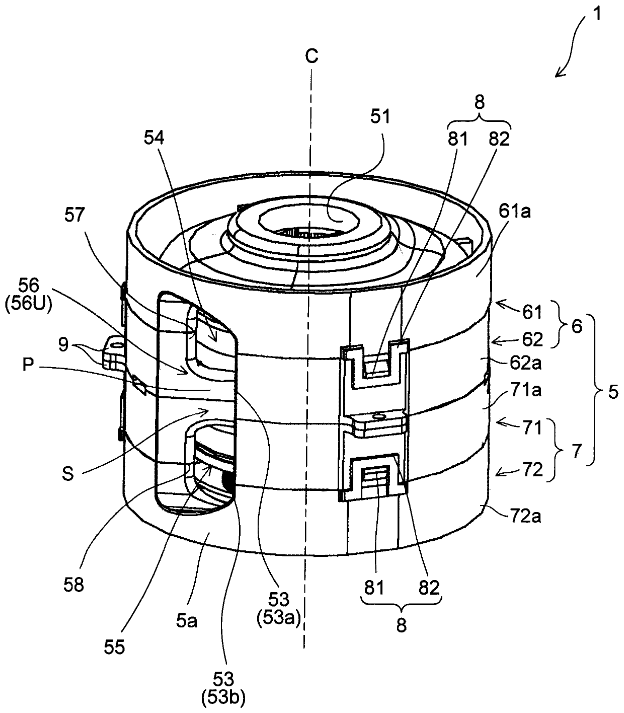
  • Air blower and air blowing device using same
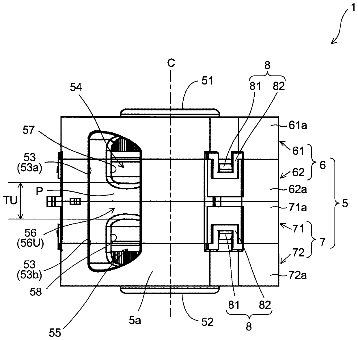
  • Air blower and air blowing device using same
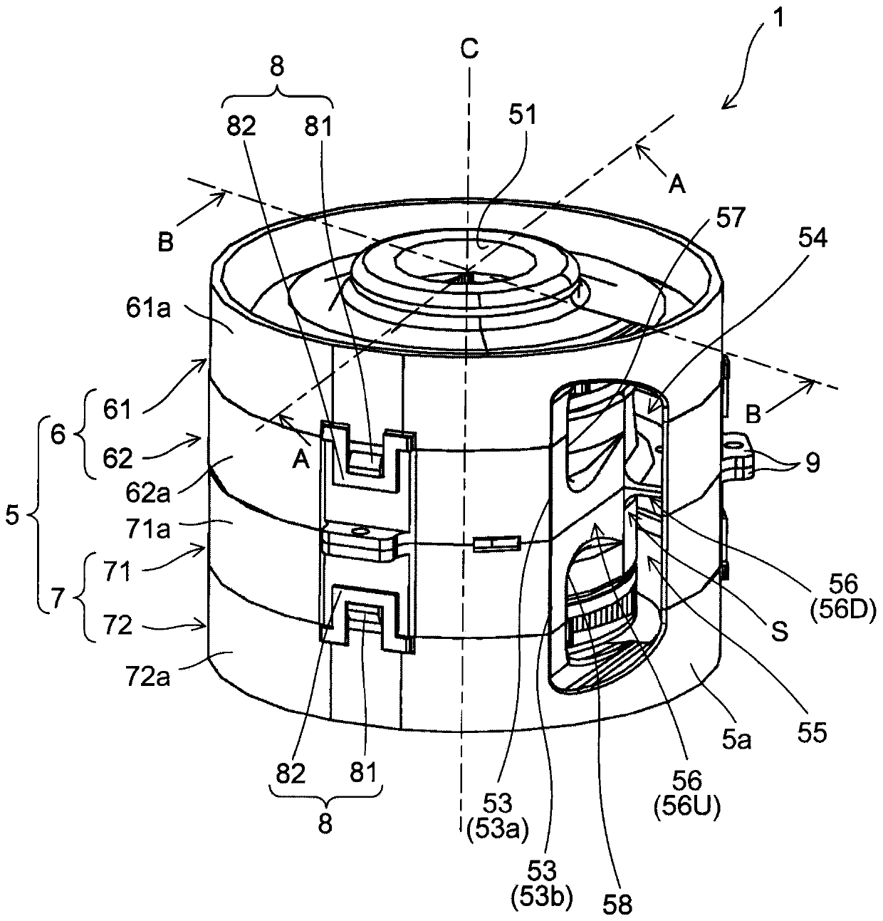
  • Air blower and air blowing device using same

Examples


Embodiment Construction

[0028] Hereinafter, exemplary embodiments of the present invention will be described in detail with reference to the drawings. In addition, in this specification, the axis|shaft which is the rotation center of the shaft of a motor is called a "center axis|shaft", and the direction in which this center axis|shaft extends is simply called an "axial direction." In addition, the direction perpendicular to the central axis starting from the central axis is simply referred to as "radial direction", and the direction along an arc drawn around the central axis is simply referred to as "circumferential direction".

[0029] In addition, in this specification, for convenience of description, the shape and positional relationship of each part are demonstrated using the axial direction as an up-down direction, and the up-down direction of a blower corresponds to the up-down direction of an axial direction. In this case, one of the axial directions is referred to as "up", and the other of t...


PUM


Abstract

The invention provides an air blower and an air blowing device using the same. A housing of the air blower has a first air inlet located closer to one side in an axial direction than a first impeller;a second air inlet located closer to the other side in the axial direction than a second impeller; an air outlet located closer to the outer side in the radial direction of a shaft than the first impeller and the second impeller; a first air tunnel communicating with the first air inlet and the air outlet; a second air tunnel communicating with the second air inlet and the air outlet; and a wallportion separating the first air tunnel and the second air tunnel in an axial direction. The first air tunnel and the second air tunnel have a first opening and a second opening on the most upstream side in the flow direction of each air flow in the circumferential direction. The thickness of the wall portion in the axial direction decreases toward the tail end of the wall portion located on the downstream side from the start end of the wall portion positioned upstream of the air flow direction in the circumferential direction.

Description

technical field [0001] The present invention relates to an air blower and an air blower using the same. Background technique [0002] Conventionally, a centrifugal blower having two impellers has been proposed. For example, in the air blower disclosed in Patent Document 1, a first impeller and a second impeller are respectively connected to both ends of the rotation shaft of the motor. When the first impeller and the second impeller are rotated, air is sucked into the case from both ends in the axial direction. This air travels circumferentially within the box. [0003] A wind tunnel (hereinafter, also referred to as a first wind tunnel) forming a flow path of air traveling through the inside of the casing by rotation of the first impeller is provided inside the casing. In addition, a wind tunnel (hereinafter also referred to as a second wind tunnel) for forming a flow path of air that travels through the device as the second impeller rotates is provided inside the case. ...

Claims


Application Information

Patent Timeline
Patent Type & Authority Applications(China)
IPC IPC(8): F04D25/08F04D29/42F04D29/44F04D29/66F04D29/70
CPCF04D25/08F04D29/4226F04D29/424F04D29/441F04D29/663F04D29/703
Inventor 刘俊贤李柏毅
Owner NIDEC CORP
Learn More