Rotating electrical machine and housing for rotating electrical machine

A technology for rotating electrical machines and housings, which is applied in the field of rotating electrical machines and housings of rotating electrical machines, and can solve problems such as the inability to cool the electric machine and the inability to guide air to the heat sink

Inactive Publication Date: 2014-06-25
YASKAWA DENKI KK
View PDF6 Cites 2 Cited by
  • Summary
  • Abstract
  • Description
  • Claims
  • Application Information

AI Technical Summary

Problems solved by technology

Therefore, it is sometimes not possible to direct the air to the side of the heat sink
As

Method used


Image

  • Rotating electrical machine and housing for rotating electrical machine
  • Rotating electrical machine and housing for rotating electrical machine
  • Rotating electrical machine and housing for rotating electrical machine

Examples


no. 1 approach

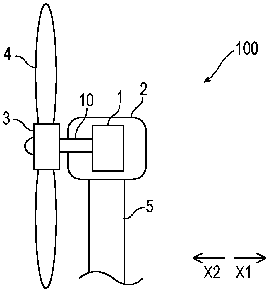
[0023] First, refer to figure 1 The configuration of the wind power generation system 100 will be described.

[0024] Such as figure 1 As shown, the wind power generation system 100 includes a generator 1 , a nacelle 2 for accommodating the generator 1 , a rotor hub 3 , blades 4 , and a tower (support column) 5 . The generator 1 is accommodated in the nacelle 2 . In addition, the rotor hub 3 is attached to a rotating shaft 10 of the generator 1 which will be described later. In addition, a plurality of blades 4 are mounted on the rotor hub 3 . In addition, the nacelle 2 is mounted on a tower 5 .

[0025] Below, refer to Figure 2 to Figure 7 The configuration of the generator 1 according to the first embodiment will be described. In addition, the generator 1 is an example of a "rotating electric machine".

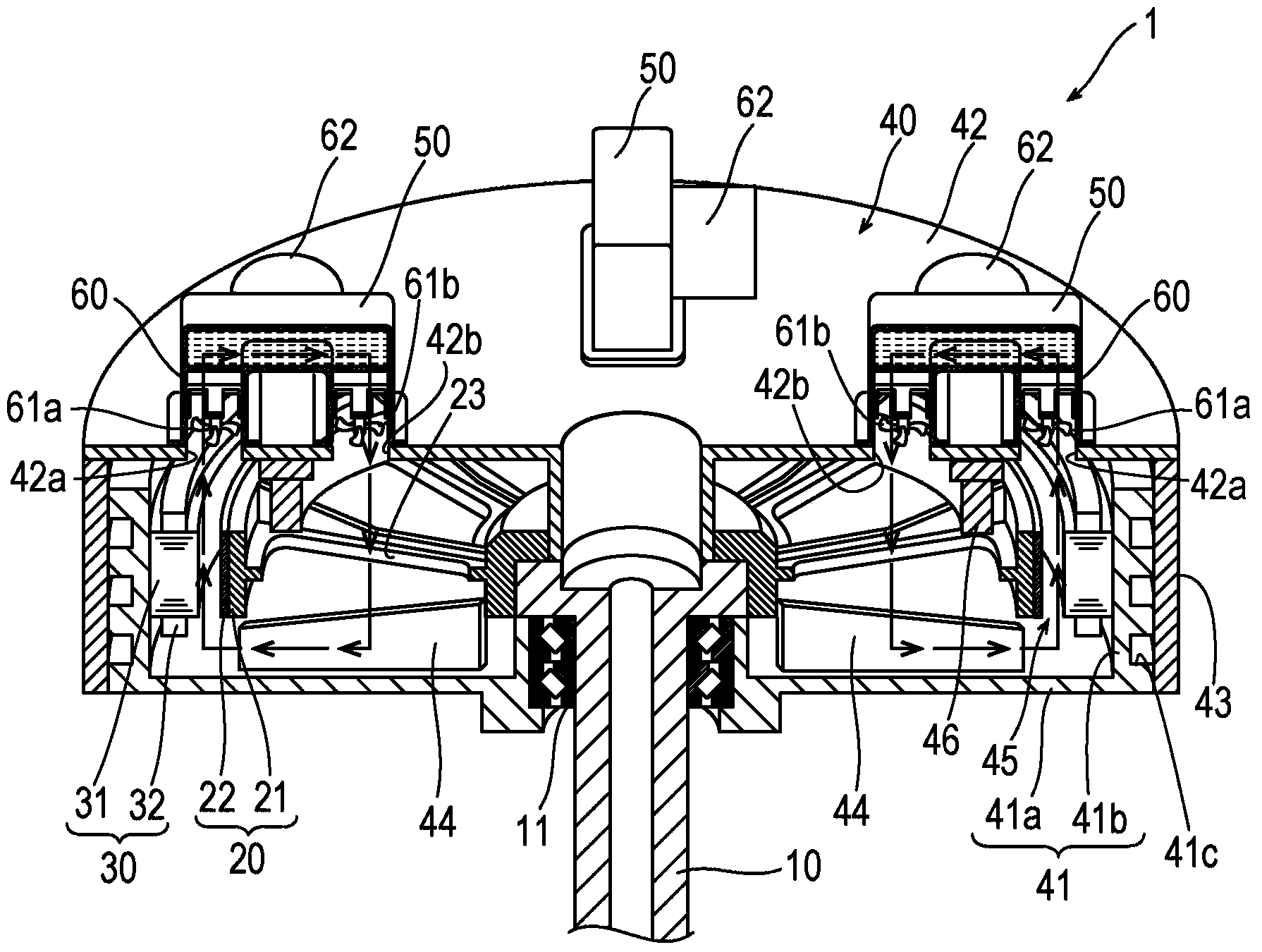
[0026] Such as figure 2 and image 3 As shown, the generator 1 includes a rotating shaft 10 , a rotor 20 , a stator 30 , a case 40 for accommodating the rotor 20 ...

no. 2 approach

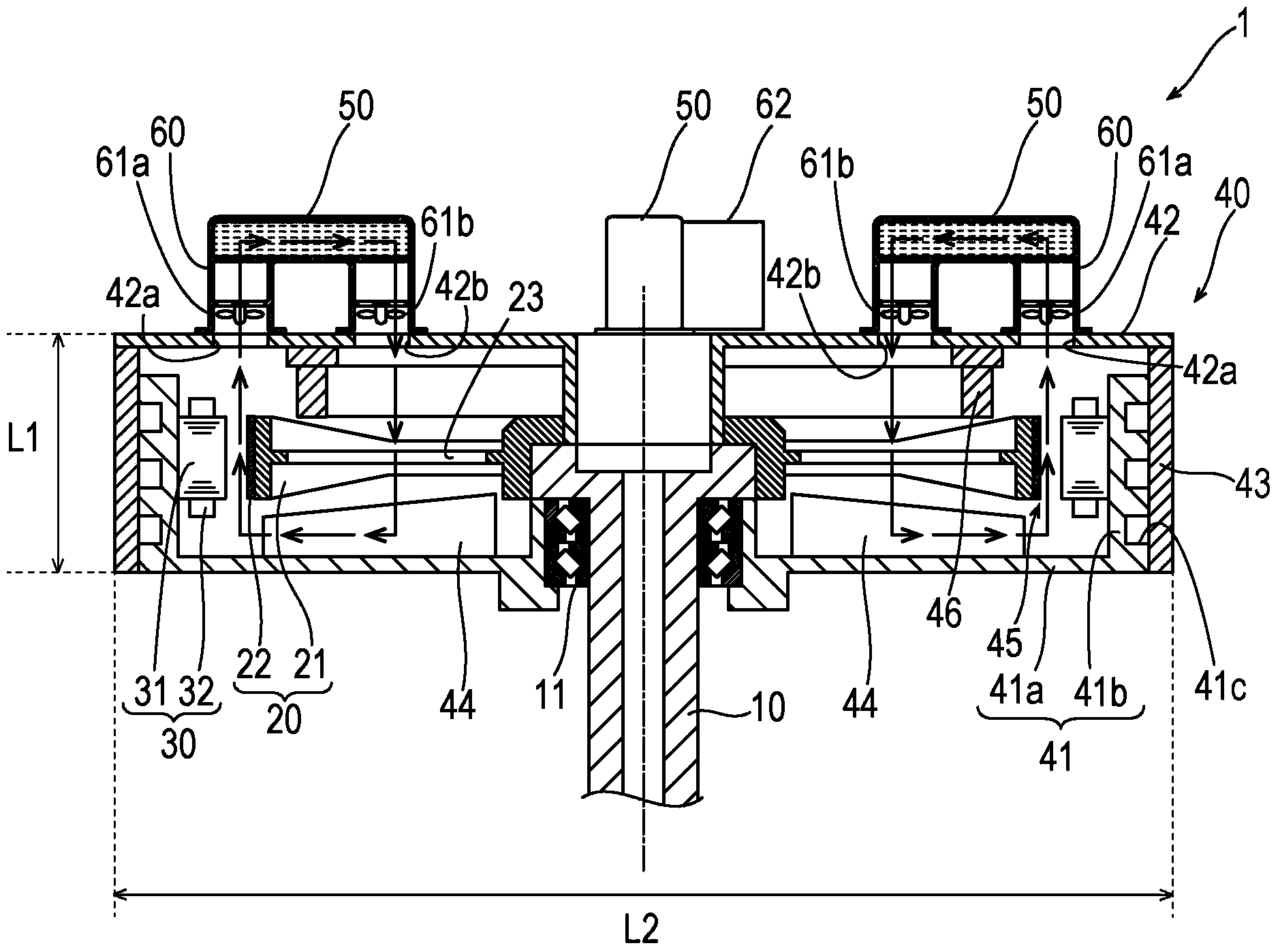
[0056] Refer below Figure 8 ~ Figure 11 The configuration of the generator 101 of the second embodiment will be described. In addition, in the second embodiment, the generator 101 is a generator for wind power generation. In addition, the generator 101 is an example of a "rotating electric machine".

[0057] Such as Figure 8 As shown, the generator 101 includes a rotating shaft 110 , a rotor 120 , a stator 130 , a housing 140 for accommodating the rotor 120 and the stator 130 , and a heat exchanger 150 . The rotating shaft 110 is connected to the rotor 120 . In addition, a bearing 111 is provided between the rotating shaft 110 and the housing 140 . In addition, the housing 140 includes brackets 141 and 142 and a sheath 143 .

[0058] Such as Figure 8 As shown, the stator 130 is arranged to face the outer peripheral portion of the rotor 120 . Additionally, if Figure 8 , Figure 9 and Figure 10 As shown, the stator 130 includes: a stator core 131; and a slot 132 w...


PUM


Abstract

A housing (40, 140) of a rotating electrical machine (10, 101), includes: a plurality of heat exchangers (50, 150) attached to an outer surface of the housing to cool a gas circulating in the housing; and a first partition wall portion (44, 144) disposed in an interior of the housing to partition the interior of the housing.

Description

[0001] Cross References to Related Applications [0002] This application is based on Japanese Patent Application No. 2012-277942 submitted to the Japan Patent Office on December 20, 2012 and Japanese Patent Application No. 2013-202274 submitted to the Japan Patent Office on September 27, 2013. The contents are incorporated herein by reference. technical field [0003] The present invention relates to a rotating electrical machine and a casing of the rotating electrical machine. Background technique [0004] Conventionally, an electric machine including a stator and a rotor is known (see, for example, JP 2002-537748 A). Japanese Patent Application Laid-Open No. 2002-537748 discloses a rotor fixed to a rotating shaft and a stator provided to face the rotor. In this electric machine, the rotating shaft is formed in a hollow shape. In addition, an impeller is attached to an axial end portion of the rotor. In addition, a cooling fin is provided on one outer side (one side) i...

Claims


Application Information

Patent Timeline
IPC IPC(8): H02K5/04H02K9/00H02K9/04H02K5/20H02K1/20H02K1/32H02K21/14
CPCH02K9/04H02K9/08H02K9/19Y02E10/72H02K9/12H02K5/203H02K9/227H02K1/20H02K5/20H02K21/14H02K1/32
Inventor 宫本恭祐广渡光太朗津曲宏
Owner YASKAWA DENKI KK
Why Eureka
Try Eureka