Progressive roller centrifugal brake

A centrifugal brake, progressive technology, applied in the direction of brake types, automatic brakes, elevators, etc., can solve the problems of vibration, damage to the elevator, large volume, etc., and achieve the effect of smooth and balanced braking, long service life and simple structure

Pending Publication Date: 2020-03-17
SHENZHEN SHENGSHI ELEVATOR CO LTD
View PDF0 Cites 2 Cited by
  • Summary
  • Abstract
  • Description
  • Claims
  • Application Information

AI Technical Summary

Problems solved by technology

[0003] However, the existing centrifugal brake is an instantaneous braking method, which will not only affect and damage the structure of the car and the transmission part of the elevator, but also cause serious vibrations if the passenger is in the car when the elevator stops, causing serious shock to the passenger. In addition, the existing centrifugal brake has a long length, large volume, low space utilization rate, and cannot be miniaturized

Method used


Image

  • Progressive roller centrifugal brake
  • Progressive roller centrifugal brake
  • Progressive roller centrifugal brake

Examples


Embodiment Construction

[0037] Below, the present invention will be further described in conjunction with the accompanying drawings and specific implementation methods. It should be noted that, under the premise of not conflicting, the various embodiments described below or the technical features can be combined arbitrarily to form new embodiments. .

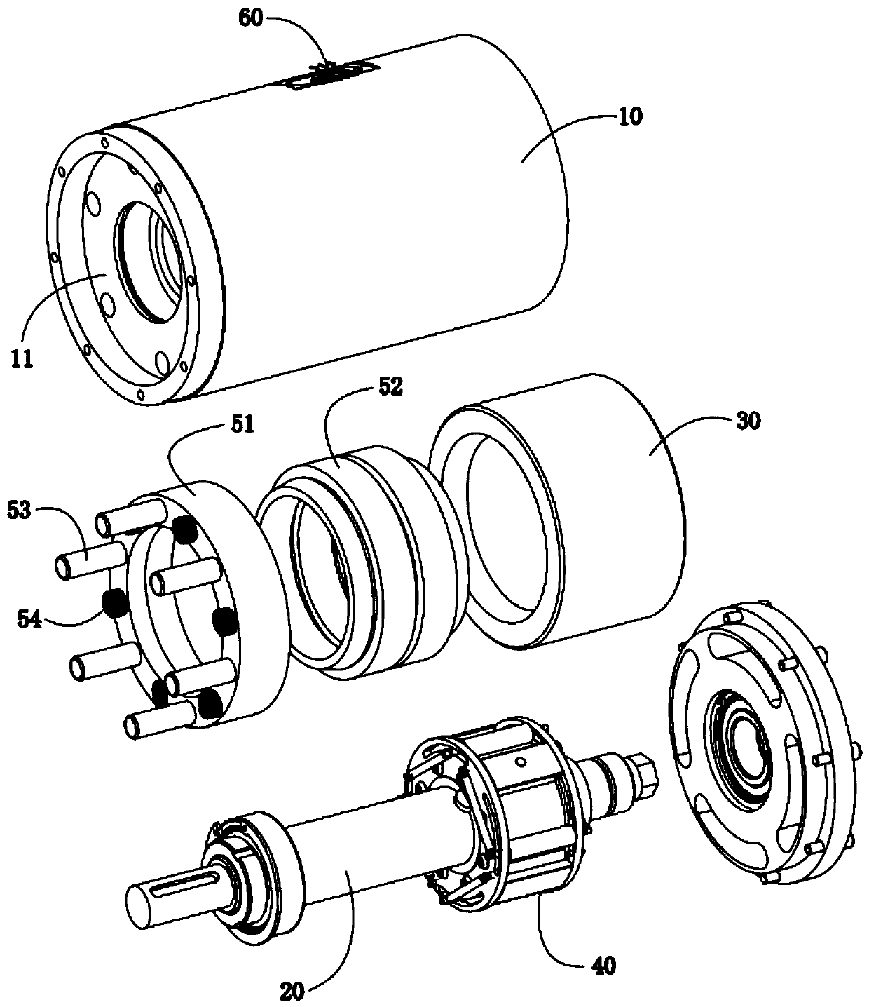
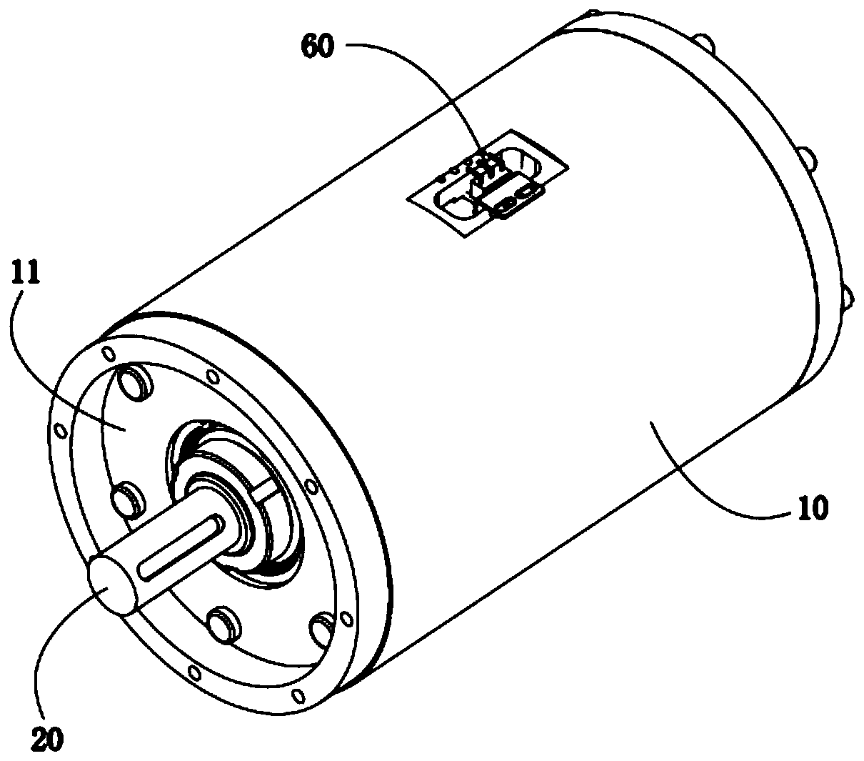
[0038] Such as Figure 1-14 The progressive roller centrifugal brake shown includes a housing 10 and a rotating shaft 20 disposed in the housing 10. The housing 10 is provided with a shaft sleeve 30 threaded therewith, and the rotating shaft 20 is provided with A centrifugal mechanism 40 that cooperates with the shaft sleeve 30 to drive the shaft sleeve 30 to rotate, and a braking mechanism 50 that axially restricts the shaft sleeve 30 to achieve braking. The centrifugal round table 41 with the gap fit of the sleeve 30, the roller 42 which is arranged between the centrifugal round table 41 and the shaft sleeve 30 and is slidably connected with the cen...


PUM


Abstract

The invention discloses a progressive roller centrifugal brake which comprises a shell and a rotary shaft. A shaft sleeve is arranged in the shell; a centrifugal mechanism which can drive a driving shaft sleeve to rotate under the action of a centrifugal force and a brake mechanism which limits the shaft sleeve axially are arranged on the rotary shaft; the centrifugal mechanism comprises a centrifugal circular truncated cone, a roller and an elastic part, and the centrifugal circular truncated cone is provided with an arc-shaped chute matched with the roller. In an initial state, the roller islocated at the starting end of the arc-shaped chute under the action of the elastic part. During braking, the roller moves to a terminal of the arc-shaped chute gradually under the action of the centrifugal force till the roller is in abutted joint to the shaft sleeve. The shaft sleeve rotates along with the rotary shaft and moves toward the direction of the brake mechanism till the rotary shaftstops rotating to achieve braking. The progressive roller centrifugal brake provided by the invention not only is compact in structure and small in size, but also brakes progressively, so that the brake brakes more stably and balancely, and the reliability of the structure is improved and the service life of the structure is prolonged.

Description

technical field [0001] The invention relates to the technical field of brakes, in particular to a progressive roller centrifugal brake. Background technique [0002] The centrifugal brake in the prior art is used for braking the rotation direction of the connected object, and it is widely used in the elevator and hoist industry. Centrifugal brakes in the prior art generally adopt a throwing block type centrifugal structure. The throwing block of the centrifugal brake is thrown out with the centrifugal force, and the thrown block is clamped on the brake disc to form a limit, so as to realize emergency braking and avoid Passengers in danger due to elevator falling. [0003] However, the existing centrifugal brake is an instantaneous braking method, which will not only affect and damage the structure of the car and the transmission part of the elevator, but also cause serious vibrations if the passenger is in the car when the elevator stops, causing serious shock to the passen...

Claims


Application Information

Patent Timeline
Patent Type & Authority Applications(China)
IPC IPC(8): F16D59/02B66B5/04
CPCB66B5/044F16D59/02
Inventor 金徐凯许玉凯
Owner SHENZHEN SHENGSHI ELEVATOR CO LTD
Why Eureka
Try Eureka