
Anti-corrosion new energy storage battery

A new energy and battery technology, applied in lithium batteries, non-aqueous electrolyte batteries, battery pack components, etc., can solve the problems of surface corrosion, aging and unusability of new energy batteries, and achieve the effect of convenient and fast movement

Inactive Publication Date: 2020-03-17
杭州星柏新能源科技有限公司
View PDF0 Cites 0 Cited by
  • Summary
  • Abstract
  • Description
  • Claims
  • Application Information

AI Technical Summary

Problems solved by technology

[0004] The purpose of the present invention is to provide anti-corrosion new energy storage batteries to solve the problem that the existing new energy storage batteries in the above-mentioned background technology are directly stacked together when storing new energy storage batteries. After a long time, the surface of the new energy storage batteries may Will be corroded and aged, making it unusable

Method used


Image

  • Anti-corrosion new energy storage battery
  • Anti-corrosion new energy storage battery
  • Anti-corrosion new energy storage battery

Examples


Embodiment 1

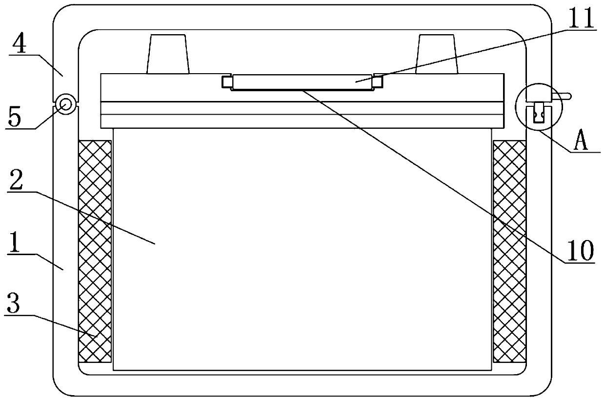
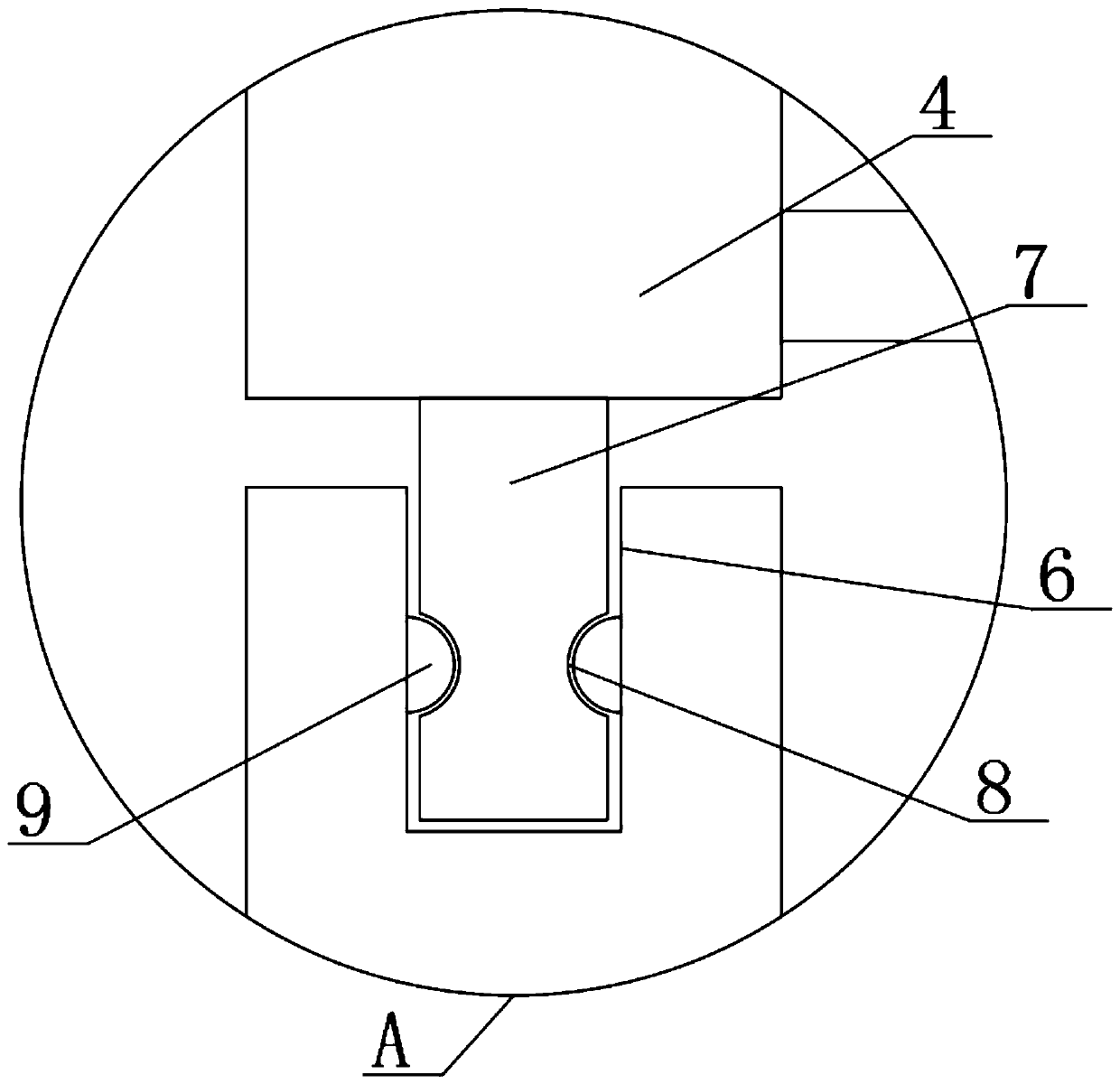
[0021] see figure 1 and figure 2 , the present invention provides a technical solution: an anti-corrosion new energy storage battery, including a protective case 1, a new energy storage battery 2 is arranged inside the protective case 1, a protective pad 3 is symmetrically fixed on the inner wall of the protective case 1, and the top of the protective case 1 A protective pad 3 is provided, and a fixed shaft 5 is connected between the protective pad 3 and the protective shell 1. The end of the protective shell 1 is provided with a connecting groove 6, and the end of the protective cover 4 is fixed with a connecting block 7. The connecting block 7 is connected to the The slot 6 is snapped and connected, the surface of the connecting block 7 is symmetrically provided with a card slot 8, and the inner wall of the connecting slot 6 is symmetrically fixed with a buckle 9, and the buckle 9 is snapped and connected with the card slot 8, which is convenient for placing the new energy ...

Embodiment 2

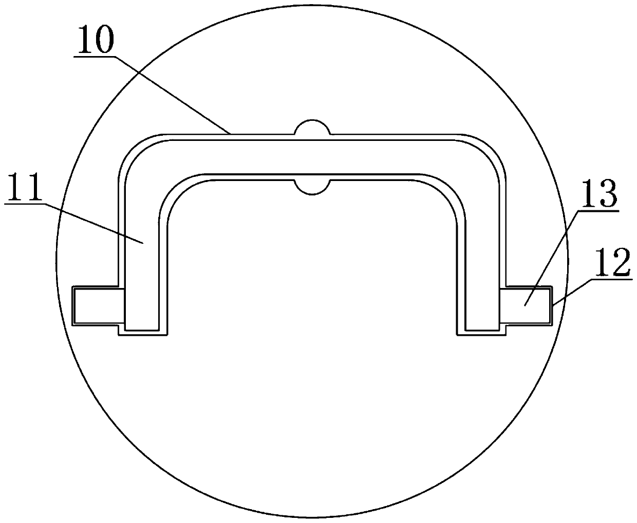
[0023] see Figure 1 to Figure 3 , the present invention provides a technical solution: an anti-corrosion new energy storage battery, including a protective case 1, a new energy storage battery 2 is arranged inside the protective case 1, a protective pad 3 is symmetrically fixed on the inner wall of the protective case 1, and the top of the protective case 1 A protective pad 3 is provided, and a fixed shaft 5 is connected between the protective pad 3 and the protective shell 1. The end of the protective shell 1 is provided with a connecting groove 6, and the end of the protective cover 4 is fixed with a connecting block 7. The connecting block 7 is connected to the The slot 6 is snapped and connected, the surface of the connecting block 7 is symmetrically provided with a card slot 8, and the inner wall of the connecting slot 6 is symmetrically fixed with a buckle 9, and the buckle 9 is snapped and connected with the card slot 8, which is convenient for placing the new energy ba...


PUM


Abstract

The invention discloses an anti-corrosion new energy storage battery. The anti-corrosion new energy storage battery comprises a protective shell, a new energy storage battery is arranged in the protective shell, and protective pads are symmetrically fixed to the inner wall of the protective shell. A protective pad is arranged at the top of the protective shell, a fixing shaft is connected betweenthe protective pad and the protective shell, and a connecting groove is formed at the end of the protective shell. A connecting block is fixed to the end of the protective cover and is connected withthe connecting groove in a clamped mode, and clamping grooves are symmetrically formed in the surface of the connecting block. According to the invention, by designing the protective shell, before thenew energy storage battery is stored, the new energy storage battery can be placed in the protective shell and then stored, so that the situation that the new energy storage battery is likely to be corroded after being used for a long time is avoided; and meanwhile, through the designed protective pad, when the new energy storage battery collides, the situation that the storage battery is damagedby collision force is avoided under the action of the protective pad.

Description

technical field [0001] The invention belongs to the technical field of new energy storage batteries, and in particular relates to anti-corrosion new energy storage batteries. Background technique [0002] New energy storage battery is a type of battery that uses lithium metal or lithium alloy as the negative electrode material and uses non-aqueous electrolyte solution. [0003] There are still some shortcomings in the use of existing new energy batteries: when the existing new energy batteries are stored, the new energy batteries are directly stacked together, and the surface of the new energy batteries may be corroded and aged in the long run , making it unusable. Contents of the invention [0004] The purpose of the present invention is to provide anti-corrosion new energy storage batteries to solve the problem that the existing new energy storage batteries in the above-mentioned background technology are directly stacked together when storing new energy storage batteri...

Claims


Application Information

Patent Timeline
Patent Type & Authority Applications(China)
IPC IPC(8): H01M2/10H01M10/052
CPCH01M10/052H01M50/20H01M50/24Y02E60/10
Inventor 不公告发明人
Owner 杭州星柏新能源科技有限公司
Learn More