
Overhead wire insulation sheath and insulating sheath coating device

A technology for overhead wires and insulating sheaths, applied in the direction of conductor/cable insulation, power cables for overhead applications, insulated cables, etc., can solve the bad society of power supply enterprises, affect the reliability and efficiency of power supply, and have a long construction period And other issues

Pending Publication Date: 2021-04-09
STATE GRID GASU ELECTRIC POWER RES INST
View PDF0 Cites 0 Cited by
  • Summary
  • Abstract
  • Description
  • Claims
  • Application Information

AI Technical Summary

Problems solved by technology

[0002] At present, more than 70% of the bare wires in the urban-rural fringe area and the rural distribution network in my country are bare wires. Whenever there is bad weather such as wind and rain, fault tripping events of distribution lines due to tree and house obstacles occur from time to time, especially Aquaculture areas are the hardest-hit areas that cause tripping of distribution network lines and electrocution deaths, seriously affecting the reliability and efficiency of power supply, and at the same time have a negative social impact on power supply companies
In the face of such problems, the traditional solution is to replace the insulated wires, which not only requires a large investment, but also has a long construction period and a large power loss due to power outages. At the same time, it is limited by geographical location, original towers and fittings design conditions, compensation for young crops, etc., power outages Influenced by factors such as time, it is difficult to implement insulation transformation in some areas and lines

Method used


Image

  • Overhead wire insulation sheath and insulating sheath coating device
  • Overhead wire insulation sheath and insulating sheath coating device
  • Overhead wire insulation sheath and insulating sheath coating device

Examples


Embodiment Construction

[0040] In order to make the purpose, technical solutions and advantages of the embodiments of the present invention clearer, the technical solutions in the embodiments of the present invention will be clearly and completely described below in conjunction with the drawings in the embodiments of the present invention. Obviously, the described embodiments It is a part of embodiments of the present invention, but not all embodiments. The components of the embodiments of the invention generally described and illustrated in the figures herein may be arranged and designed in a variety of different configurations.

[0041] Accordingly, the following detailed description of the embodiments of the invention provided in the accompanying drawings is not intended to limit the scope of the claimed invention, but merely represents selected embodiments of the invention. Based on the embodiments of the present invention, all other embodiments obtained by persons of ordinary skill in the art wi...


PUM


Abstract

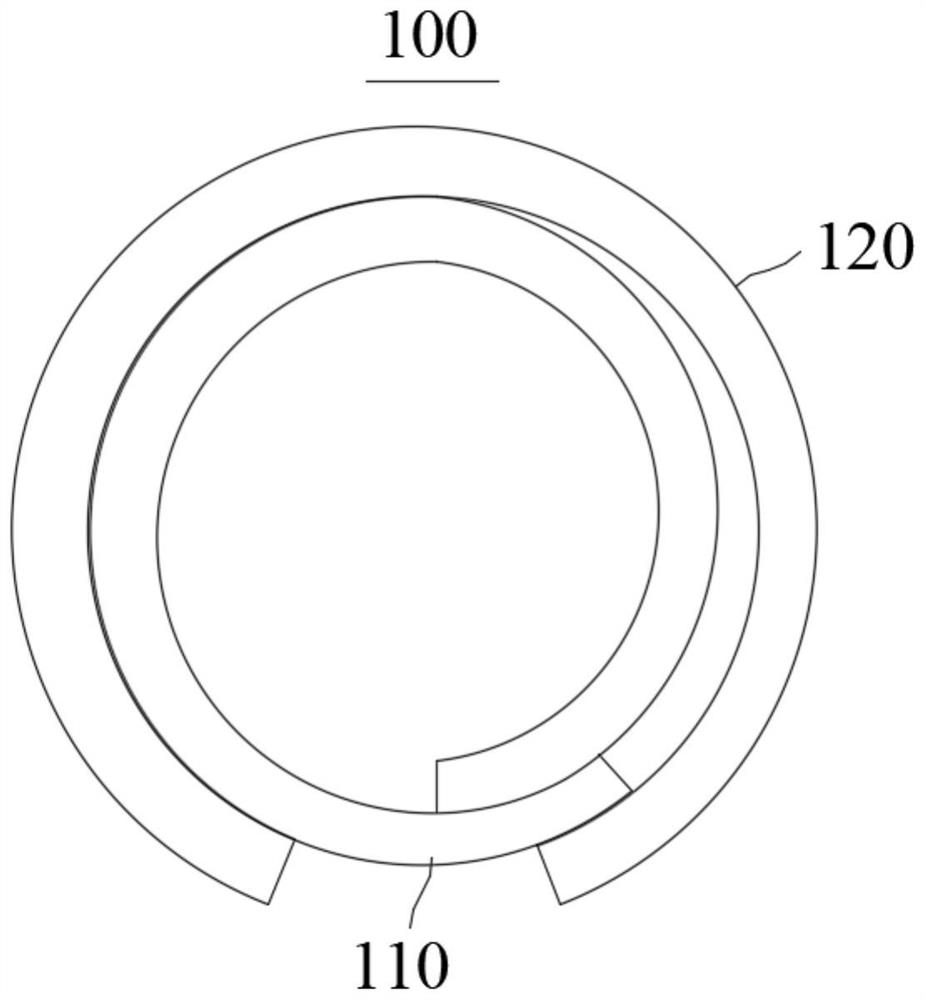
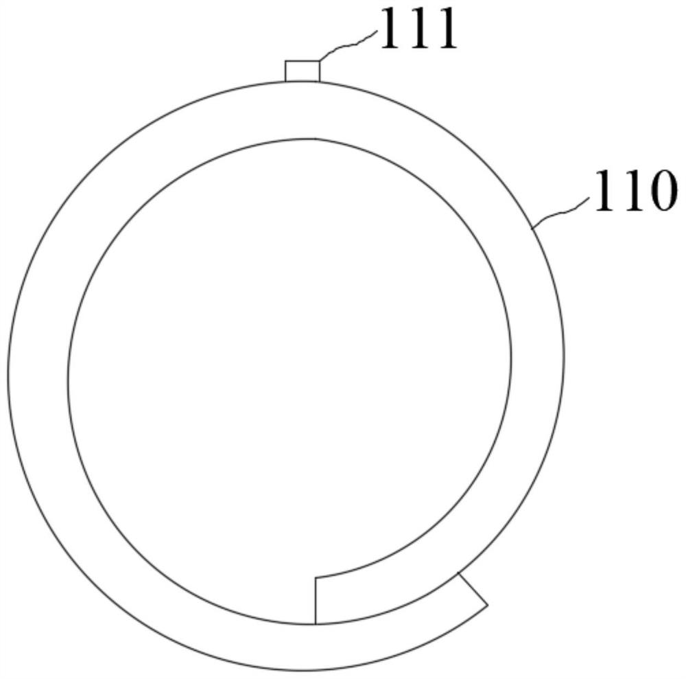
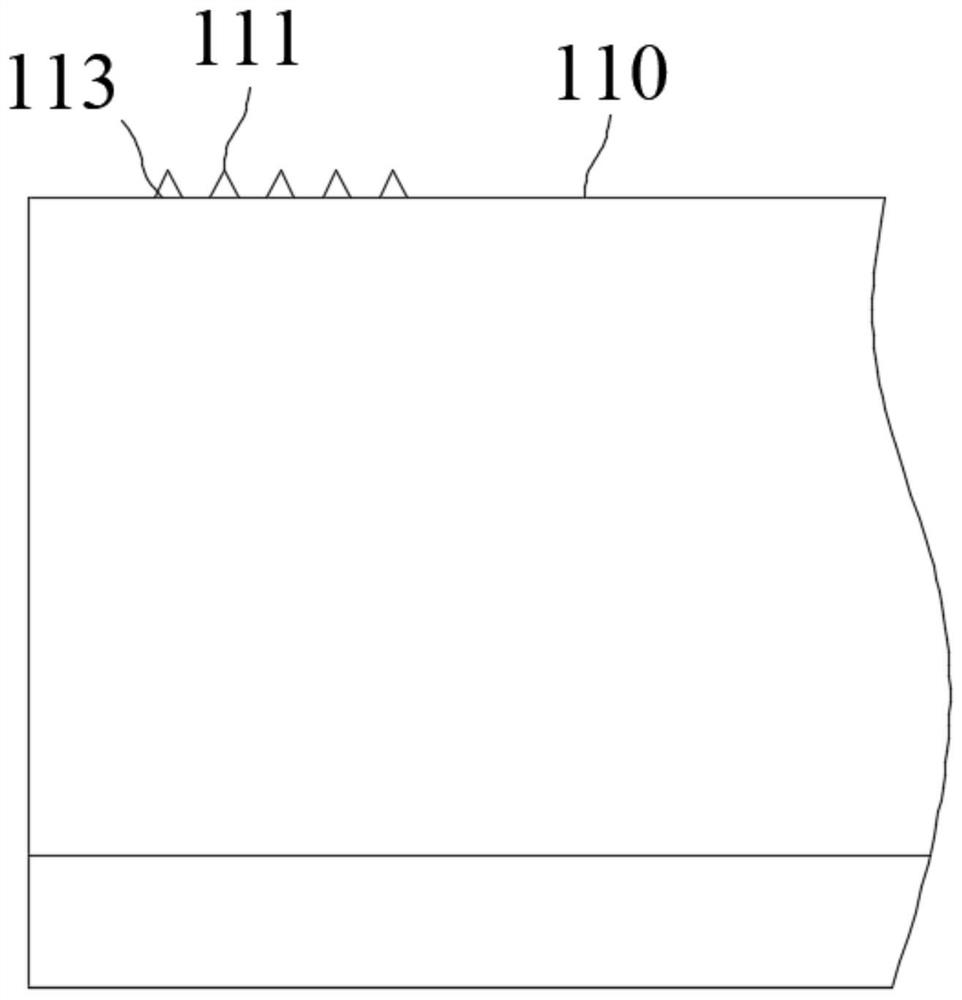
The invention relates to the field of overhead bare conductor insulation protection, in particular to an overhead wire insulation sheath and an insulation sheath coating device. The overhead wire insulation sheath comprises an insulation sheath body and a locking sheath body. The insulation sheath body can be curled under the action of the elastic force of the insulation sheath body and wraps the peripheral surface of the overhead wire; the locking sheath body can be curled under the action of the elastic force of the locking sheath body and wraps the outer peripheral surface of the insulation sheath body; through the connection between a first connecting structure arranged on the outer peripheral surface of the insulation sheath body and the second connecting structure arranged on the inner peripheral surface of a second segment, the movement of the locking sheath body relative to the insulation sheath body can be limited, so that the insulation sheathe body can be kept in a state of coating the overhead wire. The overhead wire insulation sheath can tightly wrap the peripheral surface of the overhead wire, so that the overhead wire is isolated from the outside, the wrapped overhead wire can be insulated and protected, and the overhead wire is prevented from being corroded.

Description

technical field [0001] The invention relates to the field of insulation protection for overhead bare wires, in particular to an insulation sheath for overhead wires and an insulation sheath coating device. Background technique [0002] At present, more than 70% of the bare wires in the urban-rural fringe area and the rural distribution network in my country are bare wires. Whenever there is bad weather such as wind and rain, fault tripping events of distribution lines due to tree and house obstacles occur from time to time, especially The aquaculture area is the hardest-hit area that caused the tripping of distribution network lines and the death of people by electric shock, which seriously affected the reliability and efficiency of power supply, and at the same time had a negative social impact on power supply enterprises. In the face of such problems, the traditional solution is to replace the insulated wires, which not only requires a large investment, but also has a long ...

Claims


Application Information

Patent Timeline
IPC IPC(8): H01B7/02H01B7/17H01B7/18H01B7/28H01B9/00H01B13/06H01B13/22
CPCH01B7/02H01B7/17H01B7/1805H01B7/2806H01B9/008H01B13/06H01B13/22
Inventor 杨军亭马振祺郑明果王彦彪杨佩佩张家午范迪龙张光儒何欣张秀斌高磊张海龙李亚昕
Owner STATE GRID GASU ELECTRIC POWER RES INST
Learn More