A high-redundancy synchronous signal switching method for an intelligent rectifier bridge

A synchronous signal, high-redundancy technology, applied in the direction of converting AC power input to DC power output, output power conversion devices, electrical components, etc. Information is not updated in time and other problems, so as to reduce disturbance and improve fault response speed.

Active Publication Date: 2020-09-08
THREE GORGES NENGSHIDA ELECTRIC
View PDF1 Cites 0 Cited by
  • Summary
  • Abstract
  • Description
  • Claims
  • Application Information

AI Technical Summary

Problems solved by technology

[0008] However, the synchronous disconnection fault response of this scheme is slower than that of the conventional scheme. The intelligent rectifier bridge where the fault source is located needs to judge the fault and transmit it to other intelligent rectifier bridges to start switching through communication, which adds a communication delay compared with the conventional scheme.
Moreover, if the controller receives the synchronous fault information later than the smart rectifier bridge, the synchronous phase information coordinated by the controller will not be refreshed in time, and the synchronous phase information coordinated by the controller has a higher priority than the self-selected synchronous phase, which may cause synchronous phase switching further delay, resulting in a large disturbance in the output of the smart rectifier bridge

Method used


Image

  • A high-redundancy synchronous signal switching method for an intelligent rectifier bridge
  • A high-redundancy synchronous signal switching method for an intelligent rectifier bridge
  • A high-redundancy synchronous signal switching method for an intelligent rectifier bridge

Examples


Embodiment Construction

[0028] The following will clearly and completely describe the technical solutions in the embodiments of the present invention with reference to the accompanying drawings in the embodiments of the present invention. Obviously, the described embodiments are only some, not all, embodiments of the present invention. Based on the embodiments of the present invention, all other embodiments obtained by persons of ordinary skill in the art without making creative efforts belong to the protection scope of the present invention.

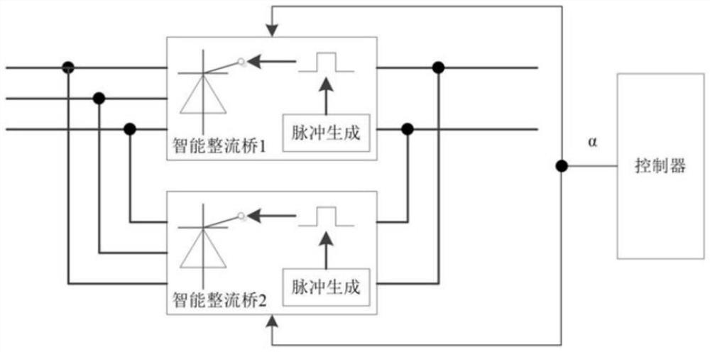
[0029] A high-redundancy synchronous signal switching method for an intelligent rectifier bridge. The intelligent rectifier bridge includes a three-phase rectifier bridge, a controller configured with an FPGA and a CPU, and the controllers of the intelligent rectifier bridge are connected via a communication network. The intelligent rectifier bridge is highly redundant The redundancy synchronization signal switching method includes the following specific steps:...


PUM


Abstract

The invention provides a high-redundancy synchronization signal switching method for an intelligent rectifier bridge, which includes acquiring three-phase synchronization signals from all rectifier bridges; the synchronization signal driving the trigger pulse comes from the local, and the synchronization signal switching is started immediately after the local synchronization signal fails; The synchronization signal that drives the trigger pulse comes from other smart rectifier bridges, and the local synchronization signal is normal. If the phase deviation of the synchronization signal that drives the trigger pulse exceeds the preset threshold compared with the local same-phase synchronization signal, synchronization signal switching is started; the local three-phase synchronization signal appears fault, and the synchronization signal driving the trigger pulse does not come from the local, select the synchronization signal driving the trigger pulse according to the synchronization signal information provided by the online controller; if the synchronization signal switching is started by the method of step S3, the online acceptance will be suspended within 1 second after the switching. Controller synchronization signal coordination. The invention improves the fault response speed of the high redundancy synchronization scheme and improves the reliability of the system.

Description

technical field [0001] The invention belongs to the field of power conversion, in particular to a method for switching high-redundancy synchronous signals of an intelligent rectifier bridge. Background technique [0002] like figure 1 As shown, high-power power electronic devices usually need to use multiple thyristor three-phase rectifier bridges to output in parallel. Conventional smart rectifier bridges can generate trigger pulses by themselves according to the control angle data output by the controller, and the trigger pulses used to drive generally use local One phase in three-phase synchronization. The test shows that for 50Hz power frequency signals, the time deviation of the same phase synchronous signal of different intelligent rectifier bridges is very small, about 10 μs, and the time deviation of synchronous signals of different phases is still large even if 120° time compensation is added, which may reach more than 50 μs . Therefore, the smart rectifier bridg...

Claims


Application Information

Patent Timeline
Patent Type & Authority Patents(China)
IPC IPC(8): H02M7/162
CPCH02M7/162
Inventor 余翔王瑞清马小高刘钰琦龚鑫超
Owner THREE GORGES NENGSHIDA ELECTRIC
Why Eureka
Try Eureka