
Heat dissipation device of new energy automobile charging pile power supply

A technology for new energy vehicles and heat sinks, applied in electrical components, electrical equipment structural parts, cooling/ventilation/heating renovation, etc. The effect of reducing the risk of safety hazards, fast heat dissipation, and high heat dissipation efficiency

Pending Publication Date: 2020-03-17
SHENZHEN WANJINGHUA TECH
View PDF0 Cites 2 Cited by
  • Summary
  • Abstract
  • Description
  • Claims
  • Application Information

AI Technical Summary

Problems solved by technology

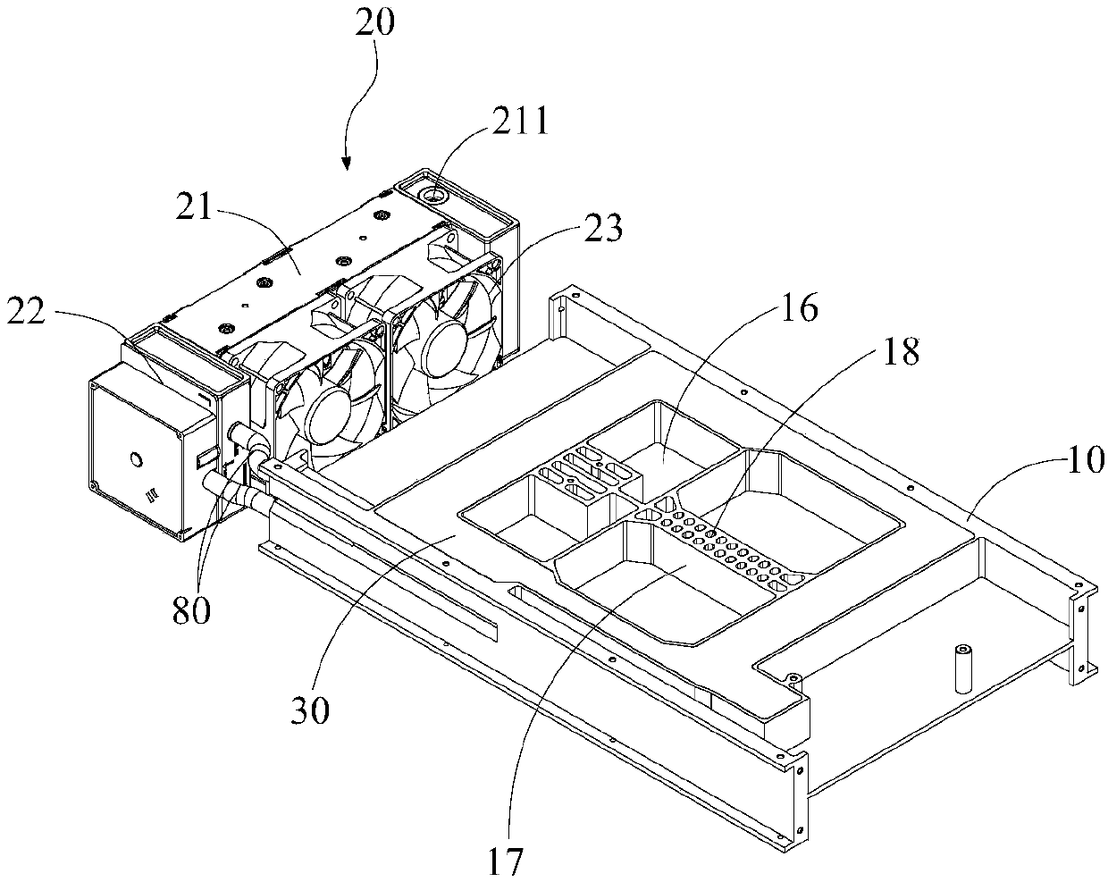
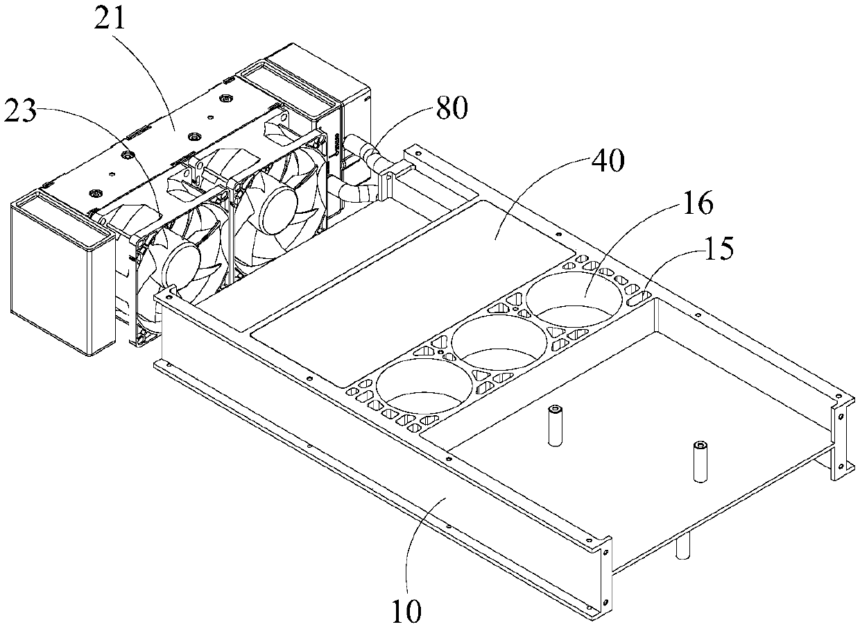
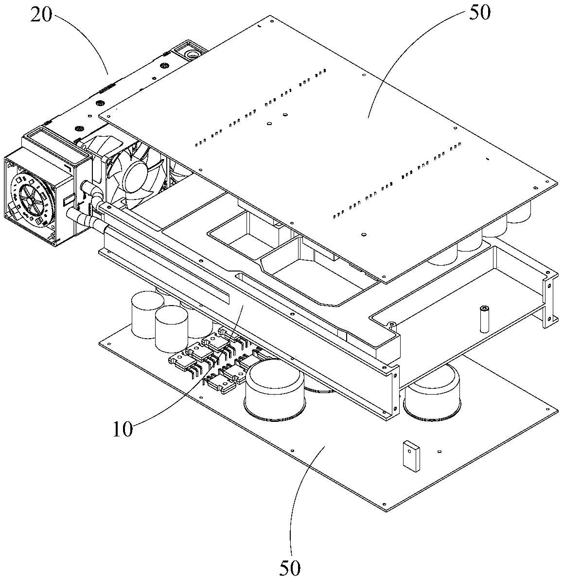
[0003] The purpose of the present invention is to provide a heat dissipation device for a charging pile power supply of a new energy vehicle, aiming at solving the technical problems in the prior art that the cooling effect of the heat dissipation device for a charging pile power supply is poor, affects charging efficiency and has potential safety hazards

Method used


Image

  • Heat dissipation device of new energy automobile charging pile power supply
  • Heat dissipation device of new energy automobile charging pile power supply
  • Heat dissipation device of new energy automobile charging pile power supply

Examples


Embodiment Construction

[0026] Embodiments of the present invention are described in detail below, examples of which are shown in the drawings, wherein the same or similar reference numerals designate the same or similar elements or elements having the same or similar functions throughout. The embodiments described below by referring to the figures are exemplary and are intended to explain the present invention and should not be construed as limiting the present invention.

[0027] In describing the present invention, it should be understood that the terms "length", "width", "upper", "lower", "front", "rear", "left", "right", "vertical", The orientation or positional relationship indicated by "horizontal", "top", "bottom", "inner", "outer", etc. are based on the orientation or positional relationship shown in the drawings, and are only for the convenience of describing the present invention and simplifying the description, rather than Nothing indicating or implying that a referenced device or element...


PUM


Abstract

The invention relates to the technical field of new energy vehicles, and a heat dissipation device of a new energy automobile charging pile power supply. The heat dissipation device comprises a heat dissipation base and a water cooling device arranged on one side of the heat dissipation base, the heat dissipation base is provided with a cooling cavity and an electronic element containing cavity. Aheat dissipation element is arranged in the cooling cavity, the water cooling device comprises a heat dissipation water row communicated with the cooling cavity and a water pump used for circularly pumping cooling liquid between the cooling cavity and the heat dissipation water row, and an upper heat absorption plate and a lower heat absorption plate are arranged on the top face and the bottom face of the cooling cavity respectively in a sealed mode. In the present invention, the upper heat absorption plate and the lower heat absorption plate can quickly transfer heat of the power supply component to the heat dissipation base; the cooling liquid cooled by the heat dissipation water row enters the cooling cavity, absorbs heat on the heat dissipation base, becomes hot water and enters the heat dissipation water row again to be cooled, the cooled water enters the cooling cavity again to absorb heat, heat exchange of the heat dissipation base is completed through circulation, rapid heat dissipation of power supply components is achieved, and the service life of the power supply is prolonged.

Description

technical field [0001] The invention relates to the technical field of new energy vehicles, and in particular provides a heat dissipation device for a charging pile power supply of a new energy vehicle. Background technique [0002] For the sake of environmental protection and energy saving, more and more electric vehicles are put on the market for use. With the advancement of society, the maturity of technology and the improvement of people's awareness of environmental protection, electric vehicles will gradually replace fuel-consuming vehicles. In the process of electric vehicles gradually replacing fuel-consuming vehicles, the charging problem of electric vehicles has always been the bottleneck hindering the rapid advancement of this process. On the charging of electric vehicles, it is mainly reflected in the number of charging piles, charging efficiency of charging piles, safety issues and many other aspects. During the charging process of electric vehicles, the power ...

Claims


Application Information

Patent Timeline
Patent Type & Authority Applications(China)
IPC IPC(8): H05K7/20
CPCH05K7/209H05K7/20927
Inventor 李俊宇
Owner SHENZHEN WANJINGHUA TECH
Learn More