Method and device using high layer syntax architecture for coding and decoding

A codec and syntax technology, applied in image communication, digital video signal modification, electrical components, etc., which can solve the problems of inefficient concealment of lost slices, and reduced decodability of slice independence.

Pending Publication Date: 2020-03-20
TENCENT AMERICA LLC
4 Cites 1 Cited by

AI-Extracted Technical Summary

Problems solved by technology

Since 2003, however, due to improvements in network architectures for delivering encoded video, as well as advances in prediction mechanisms, the concealme...

Method used

[0072] The general concept of an intra-picture prediction interruption mechanism is a complement in the specification space and the implementation space. In an embodiment, the high-level syntax structure may include independent flags, each of which corresponds to a prediction mechanism, and these flags are used to manage the prediction input of the data of a given tile, and are set in the header of the tile or in the parameter set. Therefore, this implementation may be a better, more thorough, and more resilient solution.
[0118] CPU (841), GPU (842...

Abstract

A method and device for decoding video streams. The video stream includes at least two encoded video sequences. The sequence parameter set used by each of the at least two coded video sequences differs from the sequence parameter set used by other coded video sequences by at least one value. Each of the at least two encoded video sequences includes at least two encoded images. The method includes,before decoding any one of the encoded images of the at least two encoded video sequences, the decoder decoding and enabling a single set of decoder parameters related to the at least two encoded video sequences. The method also includes the decoder decoding at least one encoded image of the at least two encoded video sequences.

Application Domain

Digital video signal modification

Technology Topic

Video streamingAlgorithm +3

Image

  • Method and device using high layer syntax architecture for coding and decoding
  • Method and device using high layer syntax architecture for coding and decoding
  • Method and device using high layer syntax architecture for coding and decoding

Examples

  • Experimental program(1)

Example Embodiment

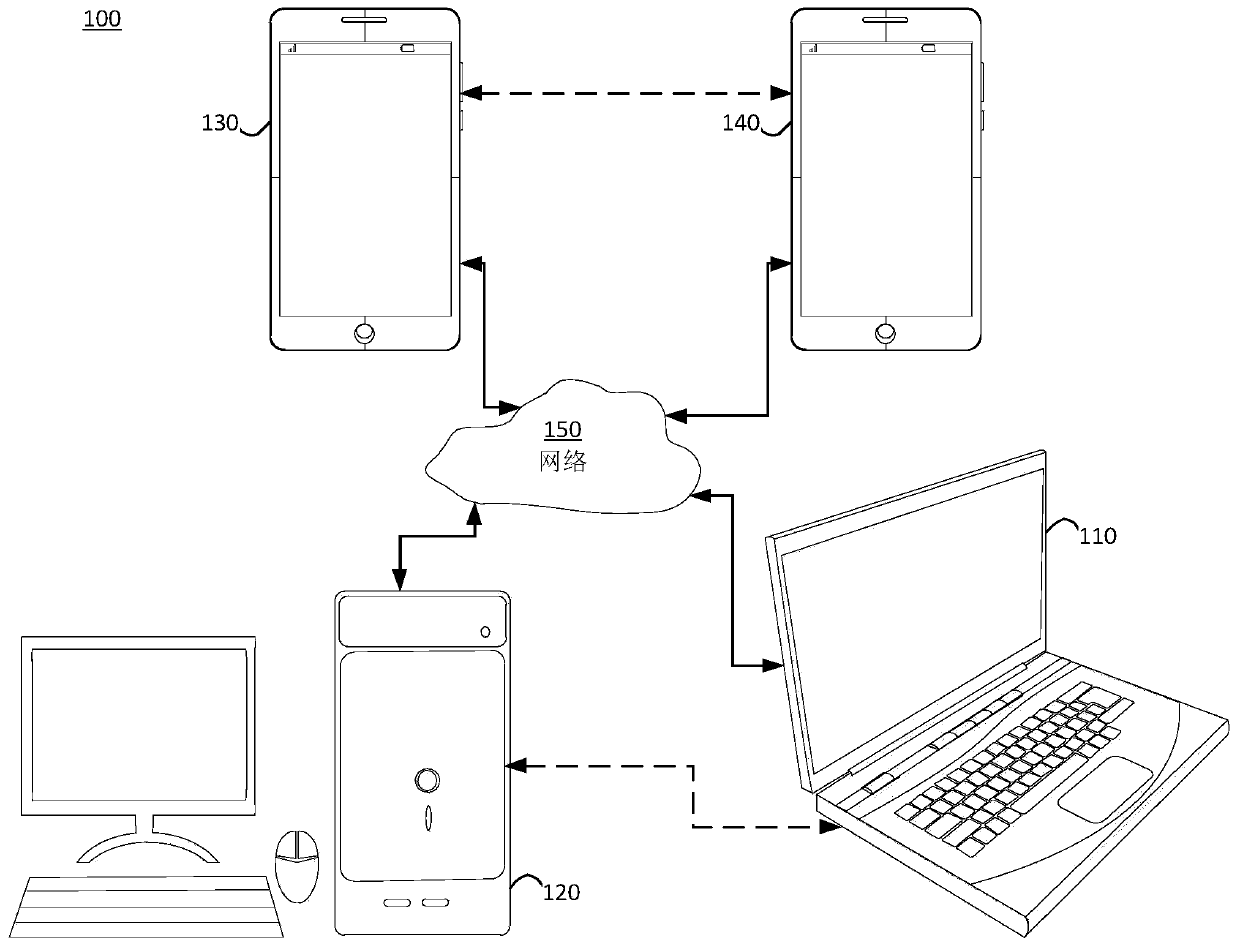
[0023] figure 1 A simplified block diagram of a communication system (100) of an embodiment of the present disclosure is shown. The system (100) may include at least two terminals (110-120) interconnected through a network (150). For one-way data transmission, the first terminal (110) may encode video data at a local location for transmission to another terminal (120) via the network (150). The second terminal (120) may receive the encoded video data of another terminal from the network (150), decode the encoded data and display the recovered video data. One-way data transmission is often used in media service applications.
[0024] figure 1 A simplified block diagram of the communication system (100) of an embodiment of the present application is shown. The system (100) may include at least two terminals (110-120) interconnected through a network (150). For one-way data transmission, the first terminal (110) may encode video data at a local location for transmission to another terminal (120) via the network (150). The second terminal (120) may receive the encoded video data of another terminal from the network (150), decode the encoded data and display the recovered video data. One-way data transmission is often used in media service applications.
[0025] figure 1 A second pair of terminals (130, 140) is shown, which can support two-way transmission of encoded video, for example, during a video conference. For two-way data transmission, each terminal (130, 140) can encode video data shot at a local location for transmission to another terminal via the network (150). Each terminal (130, 140) can also receive the encoded video data transmitted by another terminal, can decode the encoded data, and can display the recovered video data on the local display device.
[0026] in figure 1 Among them, the terminal (110-140) can be, for example, a server, a personal computer, a smart phone and/or any other type of terminal. For example, the terminal (110-140) may be a notebook computer, a tablet computer, a media player, and/or a dedicated video conference device. The network (150) represents any number of networks that can transmit encoded video data between terminals (110-140), and can include, for example, wired and/or wireless communication networks. The communication network (150) can exchange data in circuit-switched and/or packet-switched channels. Representative networks include telecommunication networks, local area networks, wide area networks, and/or the Internet. For the purpose of this discussion, unless explicitly stated, the architecture and topology of the network (150) have nothing to do with the operations disclosed in this application.
[0027] As an application example of the subject matter disclosed in this application, figure 2 Shows a way to deploy video encoders and decoders in a streaming media environment. The subject matter disclosed in this application can be used in conjunction with other video-supporting applications, including, for example, video conferencing, digital TV, and applications that store compressed video on digital media, including CDs, DVDs, and memory sticks.
[0028] Such as figure 2 As shown, the streaming media system (200) may include a shooting subsystem (213), which includes a video source (201) and an encoder (203). The streaming media system (200) may also include at least one streaming media server (205) and/or at least one streaming media client (206).
[0029] The video source (201) can be created, for example, an uncompressed video sample stream (202). The video source (201) may be, for example, a digital camera. The sample stream (202) (represented by thick lines, emphasized that the data volume is larger than the encoded video bitstream) can be processed by an encoder (203) coupled to the camera (201). The encoder (203) may include hardware, software, or a combination thereof to enable or realize various aspects of the subject matter disclosed in the present application as described in detail below. The encoder (203) can also generate an encoded video bitstream (204). The coded video bitstream (204) (represented by thin lines to emphasize that the data volume is smaller than that of the uncompressed video sample stream (202)) can be stored in the streaming server (205) for subsequent use. One or more streaming media clients (206) can access the streaming media server (205) to obtain the video bitstream (209). The video bitstream (209) may be a copy of the encoded video bitstream (204).
[0030] The streaming client (206) may include a video decoder (210) and a display (212). The video decoder (210) can, for example, decode the video bitstream (209), which is a copy of the received encoded video bitstream (204), and create an output video sample stream (211), which can be drawn on the display (212) ) Or another drawing device (not shown). In some streaming media systems, the video bitstream (204, 209) can be encoded according to some video encoding/compression standards. Examples of this standard include, but are not limited to, ITU-T recommendation H.265. The video coding standard currently under development is commonly known as Versatile Video Coding (VVC). The various embodiments disclosed in this application can be used in a VVC environment.
[0031] image 3 An example functional block diagram of a video decoder (210) connected to a display (212) according to an embodiment of the present application is shown.
[0032] The video decoder (210) may include a channel (312), a receiver (310), a buffer (315), an entropy decoder/parser (320), a scaler/inverse transform unit (351), an intra prediction unit ( 352), motion compensation prediction unit (353), aggregator (355), loop filter unit (356), reference image memory (357), and current image memory (358). In at least one embodiment, the video decoder (210) may include an integrated circuit, a series of integrated circuits, and/or other electronic circuits. Part or whole of the video decoder (210) can also be implemented by software running on one or more CPUs with associated memory.
[0033] In this embodiment and other embodiments, the receiver (310) can receive one or more coded video sequences that need to be decoded by the video decoder (210), and decode one coded video sequence at a time, wherein the decoding of each coded video sequence Independent of other coded video sequences. The encoded video sequence may be received from the channel (312), which may be a hardware/software link connected to a storage device storing the encoded video data. The receiver (310) may receive encoded video data and other data, for example, encoded audio data and/or auxiliary data stream, which may be fed forward to its corresponding entity (not shown). The receiver (310) can separate the encoded video sequence and other data. To overcome network jitter, the buffer (315) may be coupled between the receiver (310) and the entropy decoder/parser (320) (hereinafter referred to as "parser"). When the receiver (310) receives data from a storage/forwarding device with sufficient bandwidth and controllability or from an isochronous network, it may not use the cache (315) or use a small cache. For a best effort (besteffort) message network, such as the Internet, it may be necessary to use a cache (315), which may be a larger-capacity cache, or a cache with an adaptively adjusted capacity.
[0034] The video decoder (210) may include a parser (320) for reconstructing symbols (321) from the entropy coded video sequence. The classification of these symbols includes, for example, information for managing the operation of the video decoder (210), and information for controlling a drawing device. The drawing device can be coupled to figure 2 Display (212) of the decoder shown. The information used to control the drawing device may be, for example, in the form of supplementary enhancement information (SupplementaryEnhancementInformation, SEI message) or video availability information (SupplementaryEnhancementInformation, VUI) parameter set fragments (not shown). The parser (320) may parse/entropy decode the received encoded video sequence. The coding of the coded video sequence can be based on video coding technology or standards, and can follow principles known to those skilled in the art, including variable length coding, Huffman coding, arithmetic coding with or without context sensitivity, and so on. The parser (320) may extract a set of sub-group parameters corresponding to at least one sub-group of pixels in the video decoder from the encoded video sequence based on at least one parameter corresponding to a group of images. The sub-group may include group of pictures (GOP), image, tile, slice, macroblock, coding unit (CU), block, transform unit (TU), prediction unit (PU), and so on. The parser (320) can also extract information such as transform coefficients, quantizer parameter values, and motion vectors from the encoded video sequence.
[0035] The parser (320) may perform an entropy decoding/parsing operation on the video sequence received from the cache (315) to create a symbol (321).
[0036] The reconstruction of the symbol (321) may involve multiple different units according to the type of the encoded video image or some parts thereof (such as: inter-image and intra-image, inter-block and intra-block) and other factors. Which unit is involved and how is involved can be controlled by the parser (320) by the sub-group control information obtained from the coded video sequence. For clarity, the flow of subgroup control information between the parser (320) and the following multiple units is not shown.
[0037] In addition to the functional blocks already mentioned, the video decoder (210) can also be conceptually subdivided into multiple functional units as described below. In actual implementation under business constraints, multiple units interact closely with each other, and at least some units can be integrated with each other. However, in order to describe the subject matter disclosed in this application, it is appropriate to subdivide the concept of functional units below.
[0038] One unit can be a scaler/inverse transform unit (351). The scaler/inverse transform unit (351) can receive quantized transform coefficients and control information, including which transform to use, block size, quantization factor, quantization scaling matrix, etc., as symbols (321) from the parser (320). The scaler/inverse transform unit (351) can output a block including sample values, which can be input to the aggregator (355).
[0039] In some cases, the output samples of the scaler/inverse transform (351) may be related to the inner coding block; the inner coding block means that the prediction information from the previously reconstructed image is not used, but the previous image from the current image can be used. The part of the reconstructed block of prediction information. The prediction information may be provided by the intra image prediction unit (352). In some cases, the internal image prediction unit (352) generates a block of the same size and shape as the block currently being reconstructed, and generates the block using the current (partially reconstructed) image obtained from the current image memory (358) The surrounding information has been reconstructed. In some cases, for each sample, the aggregator (355) may add the prediction information generated by the intra prediction unit (352) to the output sample information provided by the scaler/inverse transform unit (351).
[0040] In other cases, the output samples of the scaler/inverse transform unit (351) may be subordinated to inter-coded blocks, possibly used for motion compensation. In this case, the motion compensation prediction unit (353) can access the reference image memory (357) to obtain samples for prediction. After motion compensation is performed on the acquired samples according to the symbol (321) associated with the block, these samples can be added to the output of the scaler/inverse transform unit (351) by the aggregator (355) (in this case, called Is residual sampling or residual signal) to generate output sampling information. The address of the prediction sample acquired by the motion compensation prediction unit (353) in the reference image memory (357) can be controlled by the motion vector. The motion vector may be used by the vector motion compensation prediction unit (353) in the form of a symbol (321), and may include, for example, x, Y and reference image components. When sub-sampled accurate motion vectors are used, vector motion compensation may also include interpolation of the sampled values ​​obtained from the reference image memory (357), motion vector prediction mechanisms, etc.
[0041] The output samples of the aggregator (355) can be processed in the loop filter unit (356) using multiple loop filtering techniques. The video compression technology can include in-loop filtering technology, which is controlled by parameters in the encoded video bitstream and can be used by the in-loop filtering unit (356) as symbols (321) from the parser (320), but also It may respond to meta-information obtained during decoding of a previous (in decoding order) part of an encoded image or encoded video sequence, and may also respond to previously reconstructed and loop-filtered sample values.
[0042] The output of the loop filtering unit (356) can be a sample stream, which can be output to a rendering device, such as a display (212), or can be stored in a reference image memory (357) for subsequent use in inter-image prediction.
[0043] Once fully reconstructed, some coded images can be used as reference images in subsequent predictions. Once the coded image is completely reconstructed and identified as a reference image (for example, the parser (320)), the current reference image stored in the current image memory (358) can become part of the reference image memory (357), and subsequent coded images are reconstructed at the beginning Previously, a new current image memory could be reassigned.
[0044] The video decoder (210) can perform the decoding operation according to the predefined video compression technology recorded in the standard, such as ITU-TRec.H.265. The coded video sequence can follow the video compression technology or standard grammar specified in the video compression technology document or standard, especially its summary document. In this sense, the coded video sequence follows the video compression technology or standard specified Grammar. Moreover, in order to comply with some video compression technologies or standards, the complexity of the encoded video sequence may be within the limits defined by the level of the video compression technology or standard. In some cases, each level imposes restrictions on the maximum image size, the maximum frame rate, the maximum reconstruction sampling rate (for example, measured in mega samples per second), the maximum reference image size, and so on. In some cases, the restriction of the level setting may be further defined by assuming a reference decoder (Hypothetical Reference Decoder, HRD) specification and the metadata of the HRD buffer management indicated in the encoded video sequence.
[0045] In one embodiment, the receiver (310) may receive additional (redundant) data along with the encoded video. The additional data may be part of the encoded video sequence. The additional data can be used by the video decoder (210) to properly decode the data and/or reconstruct the original video data more accurately. The additional data may be in the form of time, space, or signal-to-noise ratio (SNR) enhancement layer, redundant slices, redundant images, forward error correction codes, etc.
[0046] Figure 4 The functional block diagram of the video encoder (203) associated with the video source (201) according to an embodiment of the present application is shown.
[0047] The video encoder (203) may include an encoder, which may be, for example, a source encoder (430), an encoding engine (432), a (local) decoder (433), a reference image memory (434), a predictor (435), transmitter (440), entropy encoder (445), controller (450), and channel (460).
[0048] The encoder (203) may receive video samples from a video source (201) (not part of the encoder), and the video source (201) may capture video images to be encoded by the encoder (203).
[0049] The video source (201) can be of any suitable bit depth (for example: x-bit, 10-bit, 12-bit,...), any color space (for example, BT.601YCrCB, RGB,...) and any suitable sampling structure (for example, YCrCb4: 2:0, YCrCb4:4:4) digital video sample stream to provide the source video sequence to be encoded by the encoder (203). In the media service system, the video source (201) may be a storage device that stores previously prepared videos. In a video conference system, the video source (203) may be a camera that collects local image information as a video sequence. The video data can be provided as multiple separate images, and when viewed in sequence, these images exhibit a motion effect. The image itself can be organized as a spatial pixel array, where each pixel can include one or more samples according to the sampling structure, color space, etc. used. Those skilled in the art can easily understand the relationship between pixels and samples. The following focuses on sampling.
[0050] According to an embodiment, the encoder (203) can encode and compress the images of the source video sequence into an encoded video sequence (443) in real time or under any other time constraints required by the application. Enforcing the appropriate encoding speed is a function of the controller (450). The controller (450) can also control other functional units as described below, and can be functionally coupled to these units. For clarity, the coupling is not indicated in the figure. The parameters set by the controller (450) may include rate control related parameters (picture skipping, quantizer, λ value of rate distortion optimization technology, etc.), picture size, group of pictures (GOP) layout, maximum motion vector search range, etc. Those skilled in the art can easily understand other functions of the controller (450), which belong to the video encoder (203) optimized for a specific system design.
[0051] Some video encoders operate in a "coding loop" as understood by those skilled in the art. In simple terms, when the compression between the symbols in some video compression technologies and the encoded video bitstream is lossless, the encoding loop may include the encoding part of the source encoder (430) (responsible for creating based on the input image to be encoded and the reference image). Symbols), and a (local) decoder (433) embedded in the encoder (203) to reconstruct the symbols to create sample data that the (remote) decoder will also create. The reconstructed sample stream can be input to the reference image memory (434). Since the decoding of the symbol stream produces bit-level accurate results that are independent of the position of the decoder (local or remote), the content in the reference image memory is also accurately bit-by-bit between the local encoder and the remote encoder. In other words, the reference image samples "seen" in the prediction part of the encoder are exactly the same as the sample values ​​"seen" when using prediction during decoding. The basic principle of such reference image synchronization (and the drift that occurs when synchronization cannot be maintained, for example, due to channel errors) is known to those skilled in the art.
[0052] The operation of the "local" decoder (433) can be basically the same as that of the "remote" decoder (210), and the "remote" decoder (210) has been combined above image 3 Detailed Description. However, when the symbols are available and the entropy encoder (445) and the parser (320) can losslessly encode/decode the symbols into an encoded video sequence, the entropy decoding part of the decoder (210) includes the channel (312) and the receiver (310), cache (315) and parser (320), do not need to be completely implemented in the local decoder (433).
[0053] It can be observed at this time that in addition to the parsing/entropy decoding existing in the decoder, any decoder technology also needs to exist in the corresponding encoder in basically the same functional form. Therefore, the subject matter disclosed in this application focuses on decoder operation. The description of the encoder technology can be omitted because it can be the reverse process of the decoder technology that has been described in detail. A more detailed description is needed only in some areas, as described below.
[0054] As part of its operation, the source encoder (430) can perform motion-compensated predictive coding, which refers to one or more previously coded frames (referred to as "reference frames") in the video sequence to predictively code the input frames. In this way, the encoding engine (432) encodes the difference between the pixel block of the input frame and the pixel block of the reference frame, and the reference frame can be selected as a prediction reference for the input frame.
[0055] The local video decoder (433) can decode the encoded video data of the designated reference frame based on the symbols created by the source encoder (430). Advantageously, the operation of the encoding engine (432) can be a lossy process. When encoding video data in the video decoder ( Figure 4 When not shown) is decoded, the reconstructed video sequence can usually be a copy of the source video sequence with some errors. The local video decoder (433) replicates the decoding process performed by the video decoder on the reference frame, and can store the reconstructed reference frame in the reference image memory (434). In this way, the encoder (203) can locally store a copy of the reconstructed reference frame, which has common content with the reconstructed reference frame to be obtained by the remote video decoder (there is no transmission error).
[0056] The predictor (435) may perform a predictive search for the encoding engine (432). That is, for a new frame to be encoded, the predictor (435) can search the reference image memory (434) for sample data (as candidate reference pixel blocks) or some metadata that are suitable as a prediction reference for the new image, such as reference image motion Vector, block shape, etc. The predictor (435) can process the sample blocks pixel by pixel to find a suitable prediction reference. In some cases, according to the search result obtained by the predictor (435), the input image may have a prediction reference taken from a plurality of reference images stored in the reference image memory (434).
[0057] The controller (450) can manage the encoding operation of the video encoder (430), including, for example, setting parameters and subgroup parameters for encoding video data.
[0058] The output of all the above functional units can be entropy-encoded in the entropy encoder (445). The entropy encoder performs lossless compression on the symbols generated by various functional units according to techniques known to those skilled in the art, such as Huffman coding, variable length coding, and arithmetic coding, so as to convert the symbols into an encoded video sequence.
[0059] The transmitter (440) can buffer the encoded video sequence created by the entropy encoder (445) to prepare for transmission through the communication channel (460), which can be a storage device leading to the storage of encoded video data Hardware/software links. The transmitter (440) may combine the encoded video data from the video encoder (430) with other data to be transmitted, and the other data may be, for example, encoded audio data and/or auxiliary data stream (source not shown).
[0060] The controller (450) can manage the operation of the video encoder (203). During encoding, the controller (450) can assign a coded image type to each coded image, and the coded image type can affect the coding technology applicable to the corresponding image. For example, the image can generally be allocated as an intra image (I image), a predictive image (P image), or a bi-predictive image (B image).
[0061] The internal image (I image) can be an image that does not need to use any other frame in the sequence as a prediction source for encoding and decoding. Some video codecs allow different types of internal images, including, for example, Independent Decoder Refresh (IDR) images. Those skilled in the art are aware of the variations of I images and their corresponding applications and features.
[0062] Predictive pictures (P pictures) are pictures that can be coded and decoded using intra-frame prediction or inter-frame prediction, using at most one motion vector and reference index to predict the sample value of each block.
[0063] A bi-predictive image (B image) is an image that can be encoded and decoded using intra-frame prediction or inter-frame prediction, using up to two motion vectors and a reference index to predict the sample value of each block. Similarly, multiple predictive images can use more than two reference images and related metadata to reconstruct a single block.
[0064] The source image can generally be spatially subdivided into multiple sample blocks (for example, 4×4, 8×8, 4×8, or 16×16 sample blocks) and coded block by block. These blocks can be predicted and coded with reference to other (encoded) blocks, and other blocks can be determined according to the coding task of the corresponding image applied to the block. For example, a block of an I picture may be subjected to non-predictive coding, or may be subjected to predictive coding (spatial prediction or intra prediction) with reference to an already coded block of the same picture. The pixel block of the P image can be predicted and coded with reference to a previously coded reference image for spatial prediction or temporal prediction. The block of the B image can refer to one or two previously coded reference images, and perform predictive coding through spatial prediction or temporal prediction.
[0065] The video encoder (203) can perform encoding operations according to a predetermined video encoding technology or standard such as Recommendation ITU-TRec.H.265. In operation, the video encoder (203) can perform various compression operations, including predictive encoding operations that utilize temporal and spatial redundancy in the input video sequence. Therefore, the encoded video data can conform to the used video encoding technology or the syntax specified by the standard.
[0066] In an embodiment, the transmitter (440) may transmit additional data and encoded video. The video encoder (430) may use such data as part of an encoded video sequence. The additional data may include time/space/SNR enhancement layers, redundant images and slices, and other forms of redundant data, supplementary enhancement information (Enhancement Information, SEI) messages, visual usability information (Visual Usability Information, VUI) parameter set fragments, and the like.
[0067] The following describes some aspects of the embodiments of the present application, including the high-level syntax architecture implemented in video codec technology or standards such as multipurpose video coding (VVC).
[0068] The high-level syntax architecture may include the concept of the NAL unit of H.264 that has been proven to be usable because the concept has been adopted by at least some system specifications (including specific file formats).
[0069] Optionally, the advanced syntax architecture may not include the concept of (independent, regular) fragmentation. Since 2003 (the release date of the first version of H.264), the progress of video coding is that due to the continuous increase of intra-image prediction mechanisms and the continuous improvement of efficiency, in many cases, segmentation-based error concealment has actually become impossible. At the same time, due to the existence of these prediction mechanisms, in some cases, from the perspective of coding efficiency, the cost of using fragmentation has become quite expensive. Therefore, few recent implementations use fragmentation to achieve the required purpose (MTU size matching). Instead, basically all applications that require low latency and error resistance use image-based error resistance tools, such as internal refresh, open GOP, and scalability for non-uniform protection of the base layer.
[0070] After removing the fragments, in the advanced syntax architecture, the smallest VCL syntax unit whose entropy level can be independently decoded (that is, without parsing dependency) can be, for example, a tile or a coded image.
[0071] Independent decoding of tiles is helpful for certain application scenarios. For example, in a cube map scene. From any given point of view in space, at most three surfaces of an opaque cube are visible at the same time. Correspondingly, for the display scheme of a given viewpoint, only 3 of the hypothetical 6 square tiles constituting the code image of the cube map need to be decoded. To support this function, in the advanced syntax architecture, at least for applications that require independent tiles, independent tiles can directly replace independent slices. In other words, the slices organized in scanning order can be replaced by the rectangular slices called H.263+AnnexK. The collection of motion constraint blocks is also one of the requirements of the advanced syntax architecture.
[0072] The general concept of the intra-image prediction interruption mechanism is a supplement in the specification space and implementation space. In an embodiment, the high-level grammar framework may include independent tags, and each tag corresponds to a prediction mechanism. These tags are used to manage the prediction input of the data of a given block and are set in the block header or parameter set. Therefore, this implementation may be a better, more thorough, and more flexible solution.
[0073] In an embodiment where the advanced syntax architecture is applied, tiling can be enabled according to the profile used. For example, a very basic tiled mechanism that supports direct parallelization can be included in all profiles. And, more advanced techniques can be designated only for specific profiles. For example, the 360 ​​profile of the application cube chart may allow motion constraint independent tiles designed for the application; that is, the 6 tiles can be arranged in a specific way, such as a 3×2 arrangement or a cross arrangement. Other profiles can be used for other projection formats. For example, icosahedral projection may require more tiles, or a similar predictive interruption mechanism that can ideally handle the shape of the projection.
[0074] In addition to the aforementioned specific application-driven requirements, the encoded image becomes the smallest unit of interruption prediction. When the coded image is the smallest unit of interrupted prediction, all intra-image prediction mechanisms will not be interrupted, only the inter-image prediction mechanism will be interrupted. For example, some metadata and the motion compensation and inter-image prediction of some older video coding standards may be interrupted. In order to effectively support coded images without slices/tiles, the advanced syntax architecture of each embodiment may include an image header, which is used to carry the syntax of H.264/H.265 that is set in the slice header but belongs to the entire image element. One of the syntax elements may be reference information to the picture parameter set (PPS). The same as the information provided in the header of the previous segment, the image header is only related to the image it is associated with, and not related to subsequent images. In other words, the content of the image header is temporary, and there is no prediction between the image headers (otherwise, the image-based anti-error function will fail).
[0075] Ignoring the aspect of error resistance, the image header can be carried in the first (or only) block of the image or its own VCLNAL unit. The former is more efficient and the latter has a clearer structure.
[0076] In an embodiment, the advanced syntax architecture may include the picture parameter set (PPS) and sequence parameter set (Sequence Parameter Set, SPS) provided in the previous architecture in terms of syntax (single NAL unit), functionality, and persistence.
[0077] On top of the SPS, the high-level syntax framework may include a decoder parameter set (Decoder Parameter Set, DPS), thereby including tags, sub-profiles, and so on. During the existence of the video stream, the content of the DPS can remain unchanged until the end of the stream NAL unit is received.
[0078] In an embodiment that utilizes an advanced syntax architecture, the embodiment may need to allow the end-of-stream NAL unit to be carried externally. For example, when SIP re-invites to change the basic parameters of the stream (which have been confirmed by the decoding system), the decoder of the decoding system must be told to use a different DPS. If the information can only be sent to the decoder through the bitstream, the information needs to be processed by the start code to prevent competition, which will produce some adverse effects. Moreover, in actual applications, in some timeout situations, it may not be feasible to transmit the information through the bitstream.
[0079] In many cases, when the coded image is transmitted through the message network, the size of the coded image may be larger than the size of the maximum transmission unit (MTU). Introducing unnecessary prediction interruptions is not good for coding efficiency (after all, fragmentation is cancelled for this purpose), so it is best not to rely on tiles. Tiles have already assumed parallelization and application-specific tiled functions, which may conflict. For this reason, it is best not to rely on tiles. It can be discussed in terms of whether it is necessary to use the segmentation mechanism in the video codec in the specification space. If it is necessary to use a segmentation mechanism in a video codec, the advanced syntax architecture of each embodiment may use a segmentation mechanism, for example, H.265 "independent segmentation". Alternatively, segmentation is also provided in higher layers of the high-level syntax architecture. It should be noted that the RTP payload formats of various H.26x videos not only rely on fragmentation for encoder-based MTU size matching (used in a gateway scenario where the gateway does not perform transcoding), but also include some forms of fragmentation mechanisms.
[0080] reference Figure 5 Considering the above description, the grammar hierarchy (501) of the advanced grammar framework of each embodiment may be basically as follows:
[0081] The syntax hierarchy may include a decoder parameter set (DPS) (502), which exists during the session.
[0082] In some embodiments, the syntax hierarchy may include a Video Parameter Set (VPS) (503), which is used to combine scalable layers together, where the video parameter set is interrupted at the IDR on the boundary of each layer.
[0083] The syntax hierarchy may include a sequence parameter set (SPS) (504). The function of the sequence parameter set is basically similar to that in H.265, and its scope is to encode video sequences.
[0084] The grammatical hierarchy may include Picture Parameter Set (PPS) (505) and Picture Header (PH) (506) that are at the same semantic level and have similar scopes. That is, the image parameter set (505) and the image header (506) can cover all the coded images, but they may be different in each coded image. The image parameter set (505) can be basically similar to the function in H.265, and its range is a coded image. The image header (506) can carry constant data in the images that may be different in each image, and can also carry reference information to the image parameter set (505).
[0085] In some embodiments, the grammar hierarchy may include a tile header (TileHeader) (507), which is used in application scenarios that require tiles.
[0086] In some embodiments, the syntax hierarchy may include a Fragmentation Unit Header (508), which may be, for example, a non-independent Fragmentation Unit Header.
[0087] The syntax hierarchy may include VCL data of the encoded image, including coding unit (CU) data (509).
[0088] The interaction between the above various grammatical elements and grammatical levels will be described in detail below.
[0089] [Interaction of image header/image parameter set]
[0090] reference Image 6 , The following describes the interaction between the image header (PH) (601) and the image parameter set (PPS) (602) in conjunction with the embodiments of this application, where the image header (601) and the image parameter set (602) are syntactically the same Syntax level data, that is, for example, a coded image (509).
[0091] reference Image 6 , PH (601) and PPS (602) can include some specified syntax elements. Such as Image 6 As shown, both the PH (601) and PPS (602) of this embodiment include exactly four syntax elements. However, it is conceivable that the PH (601) and PPS (602) may, for example, have any size, have different sizes, include optional elements, and the like. One of these syntax elements, PH_pps_id (603), can be the reference information of PPS (602) in PH (601). The semantics of this syntax element can be similar to the semantics of pps_id in the fragment header in the previous video coding standard, that is, it is used to activate PPS and any downstream higher-level parameter sets, such as SPS, VPS, DPS, and other possible Happening. In PPS (602), PPS_pps_id (604) can be self-referencing information, and as the ID of the PPS when received. The image parameter set identification is an example of a syntax element. In some cases, for each bit stream that complies with the syntax structure, the value of the corresponding syntax element in PH (601) and PPS (602) must be the same.
[0092] Some syntax elements may only appear in PH (601), but not in PPS (602). At least in some cases, these syntax elements can be related to the image to which the PH (601) belongs, and can vary in different images. Therefore, adding these syntax elements to a parameter set, such as PPS (602), may be inefficient, because basically every time a new image is decoded, a new PPS (602) needs to be activated. An example of such a syntax element may be the identification of the currently processed image, such as time reference information, image sequence count, and similar information. For example, PH (601) may include POC (605). The corresponding entry in PPS (602) is marked as pic_type (606) to indicate the image type; this is an example of a syntax element that only appears in PPS (602) but not in PH (601). Correspondingly, all images that activate PPS (602) use the value of pic_type (606).
[0093] Some syntax elements may only appear in PPS (602), but not in PH (601). It is conceivable that many larger syntax elements that may or may be related to multiple encoded images but are not used for the entire encoded video sequence may belong to this type. When this syntax element is unlikely to change in different images, it may appear in the PPS (602) but not in the PH (601). Therefore, activating another PPS (602) will not cause a burden. For example, consider a complex and possibly large data set, such as a scaling matrix, which may allow some (possibly all) transform coefficients to independently select quantizer parameters. This data is unlikely to change during a typical group of pictures (GOP) process for a given picture type, such as I pictures, P pictures, and B pictures. The disadvantage of setting the zoom list information in the PH is that with each encoded image, it is necessary to retransmit the zoom list, which may be exactly the same, because the PH is temporary in nature.
[0094] However, there may be a third type of syntax element. These syntax elements may have similar names, such as pps_foo (608) and ph_foo (607), and may appear in both PPS (602) and PH (601). According to the nature of the grammatical elements, the relationship between these grammatical elements can be defined in video technology or standards, and can be different with different grammatical elements in the type.
[0095] For example, in the same or another embodiment, in some cases, the value of a syntax element in PH(601), such as ph_foo(607), can override a similarly named and semantically related syntax element in PPS(602), such as pps_foo(608), the value.
[0096] In the same or another embodiment, in some other cases, the value of another syntax element in PH(601) (such as ph_bar(609)) uses a similar name in PPS(602) (here "bar") And semantically related syntax elements, such as pps_bar(610), serve as some form of prediction information. For example, in some cases, the PH-based syntax element (609) can be added or subtracted from the similarly named and semantically related syntax element (610) in the PPS (602).
[0097] [Decoder parameter set and bitstream termination]
[0098] The Decoder Parameter Set (DPS) (502) has many similarities with the MPEG-2 sequence header, but it is a parameter set. Therefore, unlike the sequence header of MPEG-2, DPS (502) is not temporary. Some activation rules applied to the parameter set are different from the activation rules of the header such as the sequence header of MPEG-2 in that the activation time can be different from the decoding time of the parameter set or the header, respectively. Considering this important difference, SPS can be similar to the GOP header of MPEG-2, and DPS can be similar to the sequence header of MPEG-2.
[0099] DPS (502) may have a certain range, which is called a video bitstream in H.265. The video bitstream may include multiple coded video sequences (CVS). There are some elements in H.264 and H.265 that are beyond the scope of a given CVS. The first and most important one is the HRD parameter. In the specification space, for the parameters above the CVS level, H.264 and H.265 put these parameters into the SPS and require the relevant information between the activated SPS in each coded video sequence to remain unchanged. In the embodiment of the present application, the DPS can accumulate these syntax elements to form a structure that is known to multiple CVSs and remains unchanged.
[0100] One aspect not previously envisaged is how to notify the decoder in time from a given point to prepare to accept parameter sets that require different DPS. The parameter set may be, for example, DPS or SPS in which parameters that need to be kept unchanged are changed.
[0101] Although both H.264 and H.265 include the End of Stream NAL unit (EOS), the NAL unit cannot be used frequently, at least in part due to the structural deficiencies described below.
[0102] In H.264 and H.265, unlike some other NAL unit types, such as parameter sets, EOS needs to be transmitted in the coded video bitstream, and some constraints have been defined for its transmission location. For example, in H.264 or H.265, EOS cannot be set in the VCLNAL unit of the coded image. In implementation, the cooperation of an encoder or (at least) another entity that is aware of the advanced syntax constraints of the video coding standard is required to insert EOSNAL units at appropriate positions in the encoded video bitstream. In at least some situations, such collaboration is unrealistic. For example, see figure 1 Assuming that the receiving terminal is out of the network coverage and the terminal is receiving the NAL unit of the encoded image, the encoder is disconnected from the decoder and cannot provide EOSNAL units to the decoder. Because the connection is interrupted when receiving the NAL unit of the coded image, and the EOS cannot be set between the NAL units of the coded image, the receiver cannot splice the EOSNAL units. In practical applications, the receiving terminal can reset its decoder to a known recent state, but this operation can take several seconds. Although this time-consuming is acceptable for the above scenario, there may be other scenarios that require the decoder to have a faster and more reasonably defined response.
[0103] In the same or another embodiment disclosed in this application, EOS can be received as part of the video stream (as in H.264/H.265) or as out-of-band information.
[0104] reference Figure 7 In the same or another embodiment, when EOS is received (701) and processed outside the band, the decoder can stop using the effective decoder parameter set of the video stream. Stop using the effective decoder parameter set (DPS) means to enable another DPS that has at least one different value from the previous effective DPS without generating a syntax conflict.
[0105] For example, stopping the use of valid DPS may include that the decoder immediately clears its buffer (702) and stops outputting the reconstructed image (703). After stopping the use of the previous valid DPS, the decoder may prepare to receive a new video stream (704), the DPS content of the new video stream may be different from the previous DPS. The decoder can then start decoding a new video stream by (optional decoding and) enabling the previous or new DPS (705), where the new DPS can be different from the old DPS. The reception and decoding of the new DPS can occur at any time, even before EOS is received out of band. Generally, the timing of receiving and decoding a parameter set has nothing to do with the decoding process, as long as the parameter set is present when it is enabled. Thereafter, the new CVS can be decoded according to the new DPS (706).
[0106] The above-mentioned high-level grammar techniques can be implemented by computer software using computer-readable instructions, and the computer software can be physically stored in one or more computer-readable media. E.g, Figure 8 A computer system (800) suitable for implementing some embodiments disclosed in this application is shown.
[0107] The computer software can be coded with any suitable machine code or computer language, and the instruction code can be generated using assembly, compilation, linking or similar mechanisms. These instruction codes can be directly executed by a computer central processing unit (CPU), a graphics processing unit (GPU), etc., or executed through operations such as code interpretation and microcode execution.
[0108] These instructions can be executed in various types of computers or computer components, including, for example, personal computers, tablet computers, servers, smart phones, gaming devices, Internet of Things devices, etc.
[0109] Figure 8 The components shown for the computer system (800) are exemplary in nature, and are not intended to limit the use or functional scope of the computer software implementing the embodiments of the present application. The configuration of each component should not be interpreted as relying on or requiring any one component or combination of components shown in the computer system (800) of the non-limiting embodiment.
[0110] The computer system (800) may include some human-machine interface input devices. The human-machine interface input device can respond to input from one or more human users, such as tactile input (such as: keystrokes, sliding operations, digital glove movement), audio input (such as voice, clapping), and visual input (such as: Gesture), olfactory input (not shown). Human-machine interface equipment can also be used to collect some media information, which is not necessarily directly related to human conscious input, such as audio (such as: speech, music, environmental sound), images (such as: scanned images, obtained from still image cameras) Photo images), videos (such as two-dimensional video, three-dimensional video, including stereo video).
[0111] The human-machine interface input device may include one or more of the following (only one of each is shown): keyboard (801), mouse (802), touchpad (803), touch screen (810), digital gloves, joystick (805) ), microphone (806), scanner (807), camera (808).
[0112] The computer system (800) may also include some man-machine interface output devices. The human-machine interface output device can stimulate the senses of one or more human users through, for example, tactile output, sound, light, and smell/taste. The human-machine interface output device may include a tactile output device (such as a touch screen (810), a digital glove or a joystick (805) for tactile feedback, but there may also be tactile feedback devices that are not used as input devices). For example, such a device may be an audio output device (such as speakers (809), headphones (not shown)), a visual output device (such as a screen (810), including a CRT screen) coupled to the system bus 848 through a graphics adapter 850 , LCD screens, plasma screens, OLED screens, each with or without touch screen input capabilities, each with or without tactile feedback capabilities-some of them can output two-dimensional visual output, or output through such as stereo display, etc. Means to output more than three-dimensional output; virtual reality glasses (not shown), holographic display and smoke cabinet (not shown)), and a printer (not shown).
[0113] The computer system (800) may also include human-accessible storage devices and related media, such as optical media including CD/DVDROM/RW (820) with CD/DVD or similar media (821), finger drive (822), Removable hard drives or solid state drives (823), traditional magnetic media such as tapes and floppy disks (not shown), professional ROM/ASIC/PLD-based devices such as security dongle (not shown), etc.
[0114] Those skilled in the art should also understand that the term “computer-readable medium” related to the subject matter disclosed in this application does not include transmission media, carrier waves or other transient signals.
[0115] The computer system (800) may also include an interface that can connect to one or more communication networks. The network can be, for example, a wireless network, a wired network, an optical network. The network can also be a local area network, a wide area network, a metropolitan area network, a car-connected network and an industrial network, a real-time network, a delay-tolerant network, etc. Examples of networks include local area networks (such as Ethernet, wireless LAN, cellular networks, including GSM, 3G, 4G, 5G, LTE, etc.), TV wired or wireless wide-area digital networks (including cable TV, satellite TV, and terrestrial broadcast TV), Car networking and industrial networks (including CAN bus), etc. Some networks usually require an external network interface adapter, which is connected to some general data port or peripheral device bus (849) (such as the USB port of a computer system (800)); other networks are usually integrated in the computer by connecting to the system bus as described below In the core of the system (800) (for example, an Ethernet interface integrated in a PC computer system or a cellular network interface integrated in a smart phone computer system). Using any kind of network, the computer system (800) can communicate with other entities. The communication may be one-way communication, for example, only receiving (for example, broadcast TV), one-way only sending (for example, from a CAN bus to some CAN bus devices). The communication can also be two-way communication, such as communication with other computer systems using a local or wide area digital network. Each of the aforementioned network 855 and network interface 854 may adopt certain protocols and protocol stacks.
[0116] The aforementioned human-machine interface device, human-accessible storage device, and network interface can be connected to the core (840) of the computer system (800).
[0117] The core (840) may include one or more central processing unit (CPU) (841), graphics processing unit (GPU) (842), field programmable gate array (FPGA) (843) and dedicated programmable processing units in the form of 844 hardware accelerators for specific tasks. The above devices, as well as read-only memory (ROM) (845), random access memory (846), internal mass storage such as internal non-user accessible hard drives, SSDs, etc. (847), can be connected to the system bus (848) . In some computer systems, the system bus (848) can be accessed in the form of one or more physical plugs, which can be expanded with additional CPUs, GPUs, etc. Peripheral devices can be connected directly to the core's system bus (848) or to the peripheral device bus (849). The architecture of the peripheral device bus includes PCI, USB and so on.
[0118] The CPU (841), GPU (842), FPGA (843) and accelerator (844) can execute some instructions, which can be combined to form the aforementioned computer code. The computer code can be stored in ROM (845) or RAM (846). Intermediate data can also be stored in RAM (846), and permanent data can be stored, for example, in an internal mass storage device (847). Fast storage and reading of any storage device can be achieved by using a cache device, which can be closely associated with one or more CPU (841), GPU (842), mass storage (847), ROM (845), RAM(846) etc.
[0119] Computer code may be stored in the computer-readable medium for performing various computer-implemented operations. The medium and computer code may be specially designed and constructed for the purposes disclosed in this application, or may be of a type known and available to those skilled in the computer software field.
[0120] As an example and not limitation, a computer system with an architecture (800), especially a core (840), can perform functions by a processor (including CPU, GPU, FPGA, accelerator, etc.) by one or more tangible Software embodied in a computer-readable medium is generated. The computer-readable medium may be the above-mentioned medium associated with a user-accessible mass storage device, as well as some non-transitory storage devices in the core (840), such as the mass storage device (847) or ROM ( 845). The software for implementing the embodiments disclosed in this application can be stored in the above-mentioned device and executed by the core (840). The computer-readable medium may include one or more storage devices or chips as needed. The above software enables the core (840), especially the processor (including CPU, GPU, FPGA, etc.) to execute the process described herein, or some parts of the above process, including the definition of the data structure stored in RAM (846), according to The software-defined process modifies this data structure. As an additional or alternative solution, the functions of the computer system can be provided by a circuit (for example, an accelerator (844)), and the circuit can be implemented by logical hard wiring or other means. When the circuit operates, it can replace or cooperate with software to execute the process described herein, or some parts of the process. Where appropriate, said software may include logic and vice versa. Where appropriate, the computer-readable medium may include storing software for execution (such as an integrated circuit (IC)), a circuit for implementing logic to be executed, or a combination thereof. The present disclosure includes any suitable combination of hardware and software.
[0121] Although some non-limiting embodiments have been described in the disclosure of this application, there are still some implementations with minor changes, implementations in which the order is changed, and various alternative equivalent implementations within the scope of the disclosure of this application. Therefore, it should be understood that although not explicitly shown or described herein, those skilled in the art can propose a variety of systems and methods that can implement the principles disclosed in this application, and therefore these systems and methods still fall within the spirit and scope of the disclosure in this application.

PUM

no PUM

Description & Claims & Application Information

We can also present the details of the Description, Claims and Application information to help users get a comprehensive understanding of the technical details of the patent, such as background art, summary of invention, brief description of drawings, description of embodiments, and other original content. On the other hand, users can also determine the specific scope of protection of the technology through the list of claims; as well as understand the changes in the life cycle of the technology with the presentation of the patent timeline. Login to view more.
Why Eureka
Try Eureka