
Bending device of engineering machinery cab framework

A bending device and engineering machinery technology, applied in the direction of feeding device, positioning device, storage device, etc., can solve the problems of strength influence, pipe fittings are not easy to be bent, pipe fittings cannot be used for skeleton welding, etc., to avoid impact damage Effect

Pending Publication Date: 2020-03-24
徐州泓吉环锻科技有限公司
View PDF0 Cites 1 Cited by
  • Summary
  • Abstract
  • Description
  • Claims
  • Application Information

AI Technical Summary

Problems solved by technology

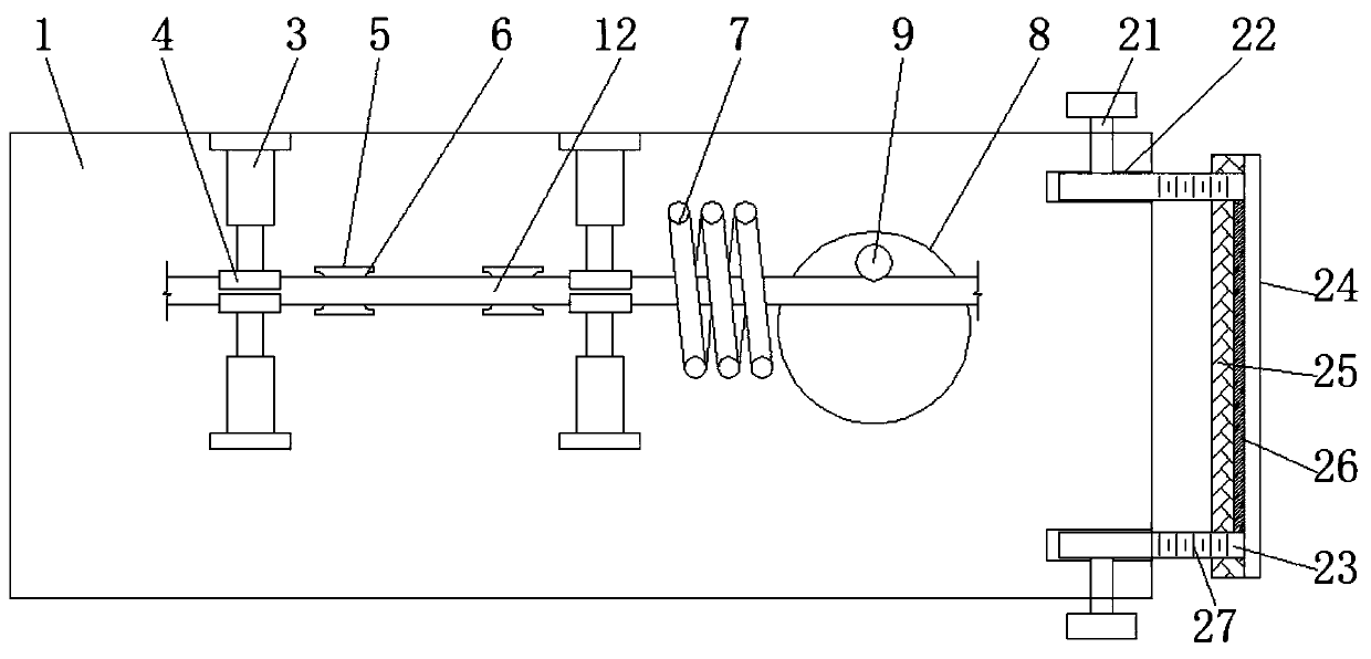
[0003] The skeleton is generally welded by hollow or solid pipe fittings. Before welding, it needs to be bent according to the shape of the cab skeleton. However, when bending, the pipe fittings are not easy to be bent, and the bending position is strong. Its strength is easily affected under the action. In addition, unlike traditional pipe fittings, there may be a groove for installing glass on the side of the skeleton pipe fitting. If the pipe clamp rolls during bending, the bent pipe fitting will not be suitable for the skeleton. welding use

Method used


Image

  • Bending device of engineering machinery cab framework
  • Bending device of engineering machinery cab framework
  • Bending device of engineering machinery cab framework

Examples


Embodiment Construction

[0027] In order to make the technical means, creative features, goals and effects achieved by the present invention easy to understand, the present invention will be further described below in conjunction with specific embodiments.

[0028] In describing the present invention, it should be understood that the terms "upper", "lower", "front", "rear", "left", "right", "top", "bottom", "inner", " The orientation or positional relationship indicated by "outside", etc. is based on the orientation or positional relationship shown in the drawings, and is only for the convenience of describing the present invention and simplifying the description, rather than indicating or implying that the referred device or element must have a specific orientation, so as to Specific orientation configurations and operations, therefore, are not to be construed as limitations on the invention.

[0029] In the description of the present invention, it should be noted that unless otherwise clearly fixed ...


PUM


Abstract

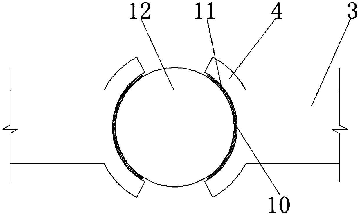
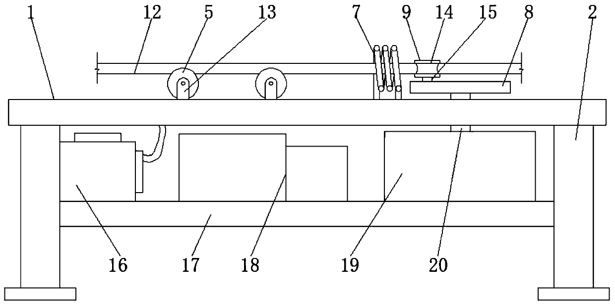
The invention discloses a bending device of an engineering machinery cab framework. The bending device comprises an operating platform and supporting feet, wherein the number of the supporting feet isfour, and the four supporting feet fixedly support four corners at the bottom of the operating platform; a clamping device and a bending device body are arranged at the upper end of the operating platform, and the clamping device comprises hydraulic cylinders, supporting blocks, rollers and supporting plates; the rollers are rotatably fixed above the operating platform through the supporting plates and bearings, and the number of the rollers is two; and the surface of each roller is provided with a supporting groove, the upper parts of the rollers are provided with a pipe fitting, and the hydraulic cylinders are fixed to the upper and lower parts, on the two sides of the rollers, of the operating platform. According to the bending device of the engineering machinery cab framework, a high-frequency pipe is arranged on the operating platform so that the bending position of a to-be-bent pipe fitting can be arranged in the high-frequency pipe to be heated, furthermore, the left side of the pipe fitting is clamped under the action of the hydraulic cylinders, when the bending operation is carried out, the bending position is more easily bent after being heated, the strength of the pipefitting cannot be influenced, and after being clamped, the pipe fitting can be prevented from rolling in the bending process.

Description

technical field [0001] The invention relates to the technical field of construction machinery processing, in particular to a bending device for the skeleton of a construction machinery cab. Background technique [0002] At present, with the acceleration of industrialization, construction machinery has been widely used in all aspects of social construction. The cab of construction machinery is the working area for operating mechanical equipment. The interior includes multiple operating levers, seats and air-conditioning systems. The mechanical cab is a separate part, which needs to be reliably connected to the frame. The cab of construction machinery is a skeleton structure, mainly composed of cab skeleton, side door and floor, and glass is installed inside the skeleton. [0003] The skeleton is generally welded by hollow or solid pipe fittings. Before welding, it needs to be bent according to the shape of the cab skeleton. However, when bending, the pipe fittings are not eas...

Claims


Application Information

Patent Timeline
IPC IPC(8): B21D7/16B21D43/00B21D37/16B21C51/00
CPCB21C51/00B21D7/16B21D7/162B21D43/003
Inventor 王犇
Owner 徐州泓吉环锻科技有限公司
Learn More