Precise machining fixture for parts of mechanical pressing machine

A mechanical press and precision machining technology, applied in the field of precision machining tooling for mechanical press parts, can solve the problems of repeated positioning accuracy or low display resolution, rotary guidance, poor positioning accuracy, affecting the accuracy of machining parts, etc. Quality and efficiency, high clamping and positioning accuracy, and the effect of improving processing efficiency

Active Publication Date: 2020-03-24
JIAMUSI UNIVERSITY
View PDF6 Cites 2 Cited by
  • Summary
  • Abstract
  • Description
  • Claims
  • Application Information

AI Technical Summary

Problems solved by technology

[0003] In order to make up for the deficiencies in the prior art, the present invention provides a precision machining tool for mechanical press parts, which solves the problem of movement in the axial and radial gaps of the workpiece and the bending plate of the fixture during the rotation process after the parts are clamped, and the rotation guide , The problem of poor positioning accuracy solves the problem of repeated positioning accuracy of the rotation tilt angle or low display resolution; solves the problem that the rigidity of the process tooling is insufficient, and it is easy to cause deformation or loosening during processing, which greatly affects the accuracy of the processed parts.

Method used


Image

  • Precise machining fixture for parts of mechanical pressing machine
  • Precise machining fixture for parts of mechanical pressing machine
  • Precise machining fixture for parts of mechanical pressing machine

Examples


Embodiment Construction

[0026] In order to clearly illustrate the technical features of this solution, the present invention will be described in detail below through specific implementation modes and in conjunction with the accompanying drawings.

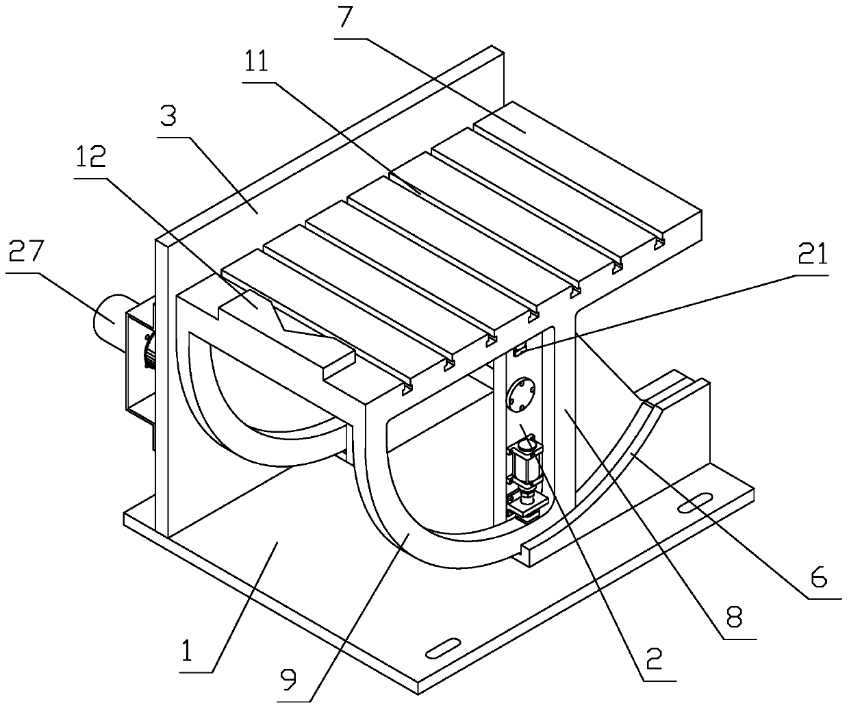
[0027] Such as Figure 1-5 As shown, a precision machining tooling for mechanical press parts, including:

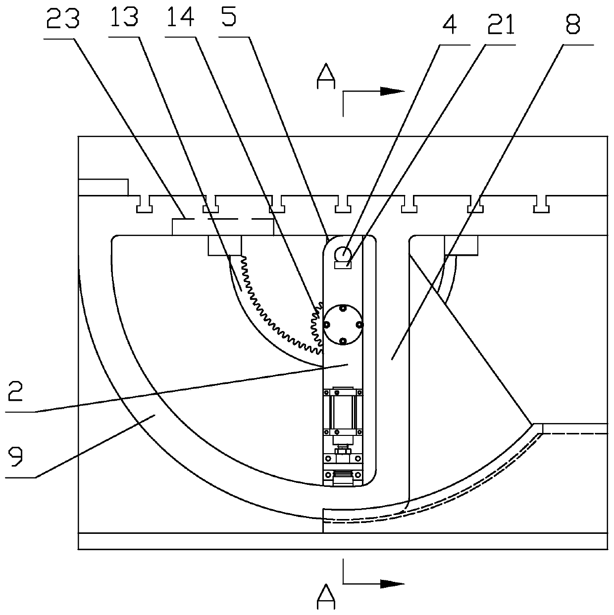
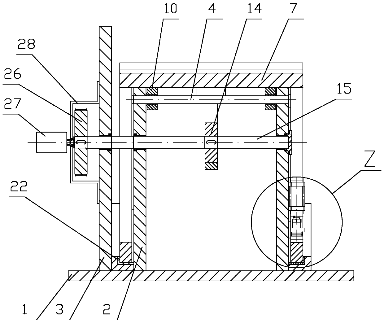
[0028] Specifically, the card includes a base plate 1, on which two support plates 2 and a side plate 3 arranged vertically at intervals are arranged, and a support shaft 4 is provided on the top of the two support plates 2, and the upper end surface of the support plate 2 is There is a 90° included angle between the front and the front surface and the transition through the rounded corners can provide in-place support for the 90° rotary table and ensure the normal rotation of the 90° rotary table. Surface rail groove 6;

[0029] 90°rotating workbench, the 90°rotating workbench includes worktable surface 7, support rod 8 and arc-shaped guide rail ...


PUM


Abstract

The invention discloses a precise machining fixture for parts of a mechanical pressing machine. The precise machining fixture for the parts of the mechanical pressing machine comprises a clamp body, a90-degree rotary workbench, and an internal gear pair, wherein the clamp body comprises a bottom plate, two support plates which are vertically arranged at an interval, and a side plate are arrangedon the bottom plate, a support shaft is arranged on the upper parts of the two support blocks, a 90-degree included angle is formed between the upper end surface and the front end surface of each support plate, and the upper end surface and the front end surface form circular-angle transition, and arc-surface guide rail grooves are formed in parts at the outer sides of the two support plates, of the bottom plate separately; the 90-degree rotary workbench comprises a workbench surface, a support rod and arc-shaped guide rails, the workbench surface is hinged to the support shaft through a self-lubricating shaft sleeve arranged at the bottom of the workbench surface, a trapezoidal groove is formed in the upper side of the workbench surface and a V-shaped location block is arranged at the upper side of the workbench surface, and the arc-shaped guide rails are movably installed in the arc-surface guide rail grooves; and the internal gear pair comprises a fan-shaped internal gear installedon the lower surface of the workbench surface. The precise machining fixture for the parts of the mechanical pressing machine has the advantages of being stable in structure, high in rigidity, capableof increasing the machining efficiency, high in clamping location assembly and rotary repeated location accuracy, and firm and reliable in brake, and the like, improves the part machining quality, and increases the part machining efficiency.

Description

Technical field: [0001] The invention relates to a precision machining tool for parts of a mechanical press. Background technique: [0002] At present, the main parts such as flywheels and support sleeves widely used in mechanical presses usually need to process long and deep oblique holes inside to lubricate the main drive rotating parts of mechanical presses, and some disc parts also need to be processed on the side. Straight, inclined hole drilling, reaming or milling of inclined surfaces. How to firmly clamp and fix parts such as flywheels, support sleeves or discs on the workbench of gantry drills, milling machines and other equipment or ground platforms, and realize the precision of long and deep inclined hole drilling, reaming or milling on oblique vertical planes , high-efficiency processing, and the existing process tooling can satisfy ordinary parts of this type with low requirements. There are many problems in the existing technical structure: on the one hand, d...

Claims


Application Information

Patent Timeline
Patent Type & Authority Applications(China)
IPC IPC(8): B23Q1/25B23Q3/04
CPCB23Q1/25B23Q3/04
Inventor 郭晓云魏天路刘明普华秀萍王树林刘羽菲康辉
Owner JIAMUSI UNIVERSITY
Why Eureka
Try Eureka