Supercharge Your Innovation With Domain-Expert AI Agents!

Heat dissipation structure for high-precision numerical control machine tool driving device

A driving device, CNC machine tool technology, applied in metal processing mechanical parts, maintenance and safety accessories, metal processing equipment, etc., can solve the problems of low safety, damaged driving device, unsatisfactory heat dissipation effect, etc., to achieve the effect of protection and safety

Inactive Publication Date: 2020-03-24
中山市睿普自动化科技有限公司
View PDF0 Cites 1 Cited by
  • Summary
  • Abstract
  • Description
  • Claims
  • Application Information

AI Technical Summary

Problems solved by technology

[0002] CNC machine tool is a high-precision, high-efficiency automatic machine tool, equipped with multi-station turret or power turret, which can process complex workpieces such as straight cylinder, oblique cylinder, arc and various threads, grooves, worms, etc. Various compensation functions such as interpolation and circular interpolation have played a good economic effect in the mass production of complex parts. However, in the work of CNC machine tools, the driving device continues to work, which will generate a lot of heat. If it is not dissipated in time, it will Affect processing and production effects, and even cause damage to the drive device
[0003] The existing heat dissipation structure used for the drive device of high-precision CNC machine tools either does not provide sufficient protection for the drive device, and the safety of the drive device is low when used in conjunction with the heat dissipation structure, or the drive device is wrapped and fixed for protection, and the heat dissipation is slow and the heat dissipation effect is poor. not ideal

Method used


Image

  • Heat dissipation structure for high-precision numerical control machine tool driving device
  • Heat dissipation structure for high-precision numerical control machine tool driving device
  • Heat dissipation structure for high-precision numerical control machine tool driving device

Examples


Embodiment Construction

[0027] In order to make the object, technical solution and advantages of the present invention clearer, the present invention will be further described in detail below in combination with specific embodiments and with reference to the accompanying drawings. It should be understood that these descriptions are exemplary only, and are not intended to limit the scope of the present invention. Also, in the following description, descriptions of well-known structures and techniques are omitted to avoid unnecessarily obscuring the concept of the present invention.

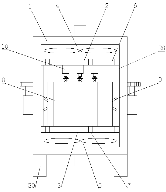
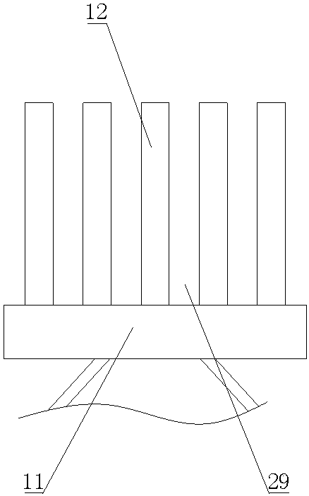
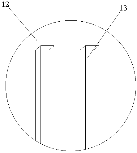
[0028] Such as Figure 1-5 As shown, a heat dissipation structure for a high-precision CNC machine tool driving device proposed by the present invention includes a housing 1, an upper partition 2, a lower partition 3, an exhaust fan 4, a blower 5, a heat conducting assembly 8, and a driving assembly 9 and the positioning assembly 10; the front and rear ends of the housing 1 are open; the upper partition 2 and the lower p...


PUM


Abstract

A heat dissipation structure for a high-precision numerical control machine tool driving device comprises a shell, an upper partition plate, a lower partition plate, an exhaust fan, an air feeder, heat conduction assemblies, driving assemblies and a positioning assembly. The front and rear ends of the shell are open; the upper partition plate and the lower partition plate are arranged at the upperend and the lower end in the shell respectively. The exhaust fan is arranged at the top end of the shell; the air feeder is arranged at the bottom end of the shell; the heat conduction assemblies arearranged on the left side and the right side of the shell and are in transmission connection with the driving assemblies on the corresponding sides. The positioning assembly is arranged on the upperpartition plate. According to the invention, the heat conduction assemblies and a fixing assembly are arranged; a heat conduction piece makes contact with the side wall of a driving device, the positioning piece abuts against the upper end of the driving device, and the driving device is firmly fixed when impacted by external force; a buffering piece generates certain buffering, and the safety ofthe driving device is effectively protected; the heat conduction assemblies, the exhaust fan and the air feeder are arranged; the heat conduction piece continuously transmits heat of the driving device outwards, meanwhile, the exhaust fan and the air feeder are started, and air circulates along an air duct to dissipate heat of the driving device in time.

Description

technical field [0001] The invention relates to the field of heat dissipation equipment, in particular to a heat dissipation structure used for a driving device of a high-precision numerical control machine tool. Background technique [0002] CNC machine tool is a high-precision, high-efficiency automatic machine tool, equipped with multi-station turret or power turret, which can process complex workpieces such as straight cylinder, oblique cylinder, arc and various threads, grooves, worms, etc. Various compensation functions such as interpolation and circular interpolation have played a good economic effect in the mass production of complex parts. However, in the work of CNC machine tools, the driving device continues to work, which will generate a lot of heat. If it is not dissipated in time, it will It will affect the processing and production effect, and even cause damage to the driving device. [0003] The existing heat dissipation structure used for the drive device o...

Claims


Application Information

Patent Timeline
IPC IPC(8): B23Q11/12
CPCB23Q11/12
Inventor 何武岗刘军宁刘文仓
Owner 中山市睿普自动化科技有限公司
Features
  • R&D
  • Intellectual Property
  • Life Sciences
  • Materials
  • Tech Scout
  • Unparalleled Data Quality
  • Higher Quality Content
  • 60% Fewer Hallucinations
Learn More