A car shock absorber bracket

A technology of automobile shock absorber and U-shaped groove, applied in suspension, elastic suspension, vehicle parts, etc., can solve the problems of gap error, different gap size, etc., and achieve the effect of improving stability and good stability

Active Publication Date: 2021-12-14
国唐汽车有限公司
View PDF12 Cites 0 Cited by
  • Summary
  • Abstract
  • Description
  • Claims
  • Application Information

AI Technical Summary

Problems solved by technology

At the same time, the design of the shock absorber bracket for fixing the shock absorber is equally important. The structural design of the existing automobile shock absorber bracket generally only passes through a fixed end of the shock absorber and is fixed on the shock absorber bracket. , and in order to avoid the shaking of the shock absorber on the shock absorber bracket, a pin sleeve sleeved on the bolt is respectively used on both sides of the fixed end of the shock absorber to abut against the fixed end of the shock absorber and the shock absorber bracket Between, but such a simple assembly method will have great disadvantages during use, especially in the case of inaccurate processing of parts (groove-shaped fixing brackets), because the size of the pin sleeve is generally fixed, and its When the limit is between the shock absorber bracket and the end of the shock absorber, due to the inevitable manufacturing errors of each shock absorber bracket during manufacture, it is also inevitable that the end of the shock absorber will There will inevitably be gap errors between the two sides, the pin sleeve and the shock absorber, and the manufacturing errors of different shock absorber brackets are different, so the gap size is also different, so it is inevitable that the shock absorber, pin sleeve and Abnormal noise of collision between shock absorbers

Method used


Image

  • A car shock absorber bracket
  • A car shock absorber bracket

Examples


Embodiment Construction

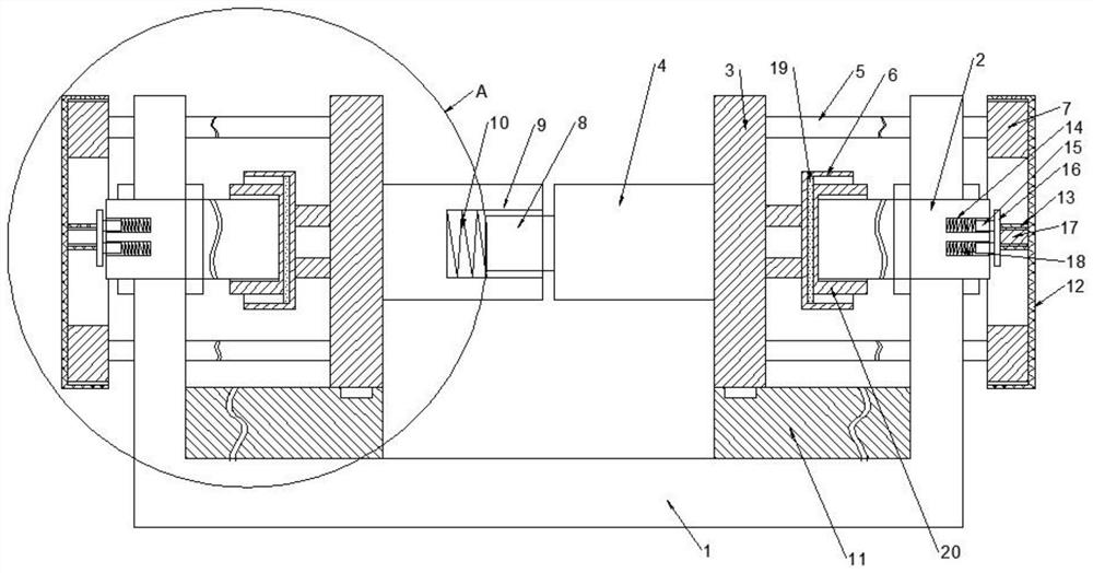
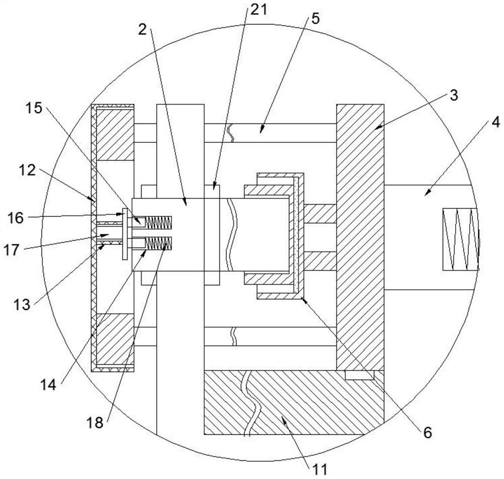
[0017] combine Figure 1 to Figure 2 The shown car shock absorber bracket, in this embodiment, includes a U-shaped channel frame 1, two sets of connecting rods 2 respectively connected to the side plates on both sides of the U-shaped channel frame 1, and two sets of clamps arranged oppositely. Tight part, one end of the connecting rod 2 passes through the U-shaped channel frame 1, and the outer side of the connecting rod 2 is also threaded with lock nuts 21 abutting on both sides of the side plate of the U-shaped channel frame 1; the clamping part includes a limit Plate 3, a central shaft 4 connected to one side of the limit plate 3, two sets of limit rods 5 connected to the other side of the limit plate 3, and a central abutment cylinder located on the limit plate 3 on the same side as the limit rod 6. The other end of the connecting rod 2 is inserted into the central abutment cylinder 6, and abuts against the bottom of the central abutment cylinder 6. Both sides of the U-sha...


PUM


Abstract

The invention provides an automobile shock absorber bracket, which includes a U-shaped channel frame, two sets of connecting rods and two groups of clamping parts. Nut; the clamping part includes a limit plate, a central shaft, at least two sets of limit rods and a central abutment cylinder, the other end of the connecting rod is inserted in the central abutment cylinder, and abuts against the bottom of the central abutment cylinder, Both sides of the U-shaped channel frame are provided with perforations for the limit rod to pass through, and a limit ring is connected to the end of the limit rod; the central rotating shafts on the two groups of clamping parts are the first rotating shaft and the second rotating shaft respectively , the first rotating shaft and the second rotating shaft are arranged oppositely, and the end of the first rotating shaft is provided with a protruding block, and the end of the second rotating shaft is provided with an insertion groove that is inserted and matched with the protruding block, and the bottom of the insertion groove The abutment spring which can be abutted on the end of the protruding block is connected, and the present invention can realize flexible clamping according to the size of the fixed end of the shock absorber, avoiding the generation of intermediate gaps, and the fixing is more reliable.

Description

technical field [0001] The invention relates to a support device, in particular to an automobile shock absorber support. Background technique [0002] As an important part of the automobile suspension system, the automobile shock absorber is mainly used to suppress the shock when the spring rebounds after absorbing the shock and the impact from the road surface. When passing through an uneven road surface, although the shock-absorbing spring can filter the vibration of the road surface, the spring There will be reciprocating motion by itself, and the shock absorber is used to suppress this spring jump. At the same time, the design of the shock absorber bracket for fixing the shock absorber is equally important. The structural design of the existing automobile shock absorber bracket generally only passes through a fixed end of the shock absorber and is fixed on the shock absorber bracket. , and in order to avoid the shaking of the shock absorber on the shock absorber bracket...

Claims


Application Information

Patent Timeline
Patent Type & Authority Patents(China)
IPC IPC(8): B60G13/00
CPCB60G13/001
Inventor 黄福良张新中康雨辰魏悦宋金行王桐陈丽蒋信智德
Owner 国唐汽车有限公司
Why Eureka
Try Eureka