3D printer wire rod winding mechanism

A 3D printer and winding mechanism technology, applied in the field of wire materials, can solve problems such as easy to be polluted by the external environment, low reliability in use, and damage to hard materials, so as to improve the utilization rate of subsequent use, improve the reliability of use, and reduce reuse Effect

Inactive Publication Date: 2020-03-24
盐城威布三维科技有限公司
View PDF4 Cites 0 Cited by
  • Summary
  • Abstract
  • Description
  • Claims
  • Application Information

AI Technical Summary

Problems solved by technology

[0002] As we all know, the printer wire winding mechanism is an auxiliary device for winding wire so that people can use the wire better. It has been widely used in the field of wire; the existing wire winding device includes a core, a core It has a cylindrical structure, and the axial direction of the core is the front and rear direction. The middle part of the core is provided with a through hole through the front and rear, and the outer front and rear sides of the core are respectively fixed and set with a left stopper and a right stopper; When the existing wire winding device is used, the produced wire is wound on the core, and the left and right stoppers are used to prevent the wire from slipping out of the core. When in use, the wire is pulled out and the core is directly rotated. The wire can be released and wound at the use position; the existing wire is found in use, it is not easy to break the wire after use, and it needs to be pulled manually, which wastes manpower, and when the wire is pulled hard, the broken part of the wire will shrink to a certain extent. The wire is uneven, which affects the next use, and the usability is poor; after the wire is used, the remaining wire is placed directly outside, which is easily polluted by the external environment or damaged by hard substances, which affects the next use and leads to reliability lower

Method used


Image

  • 3D printer wire rod winding mechanism
  • 3D printer wire rod winding mechanism
  • 3D printer wire rod winding mechanism

Examples


Embodiment Construction

[0019] In order to make the technical solution of the present invention clearer, the present invention will be further described in detail with reference to the following examples. It should be understood that the specific embodiments described here are only used to explain the invention and not to limit the invention.

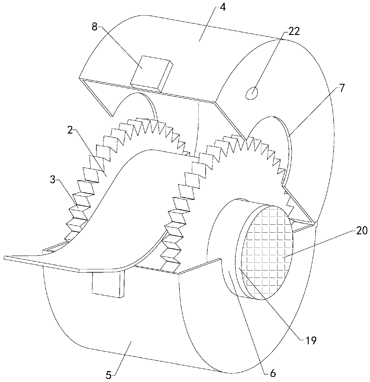
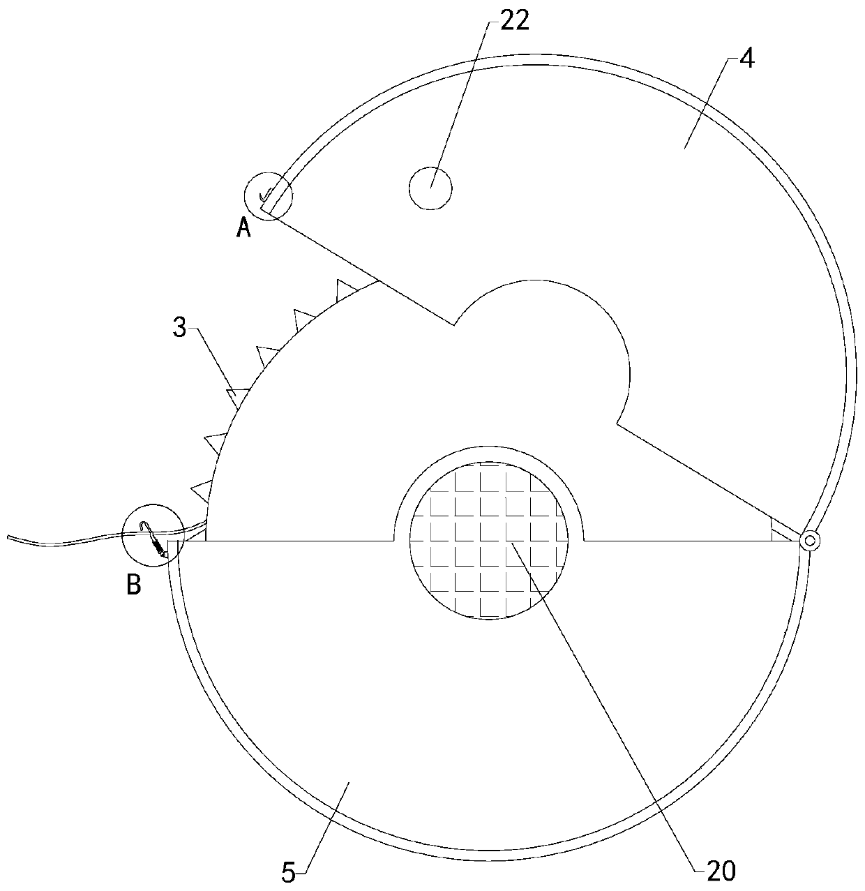
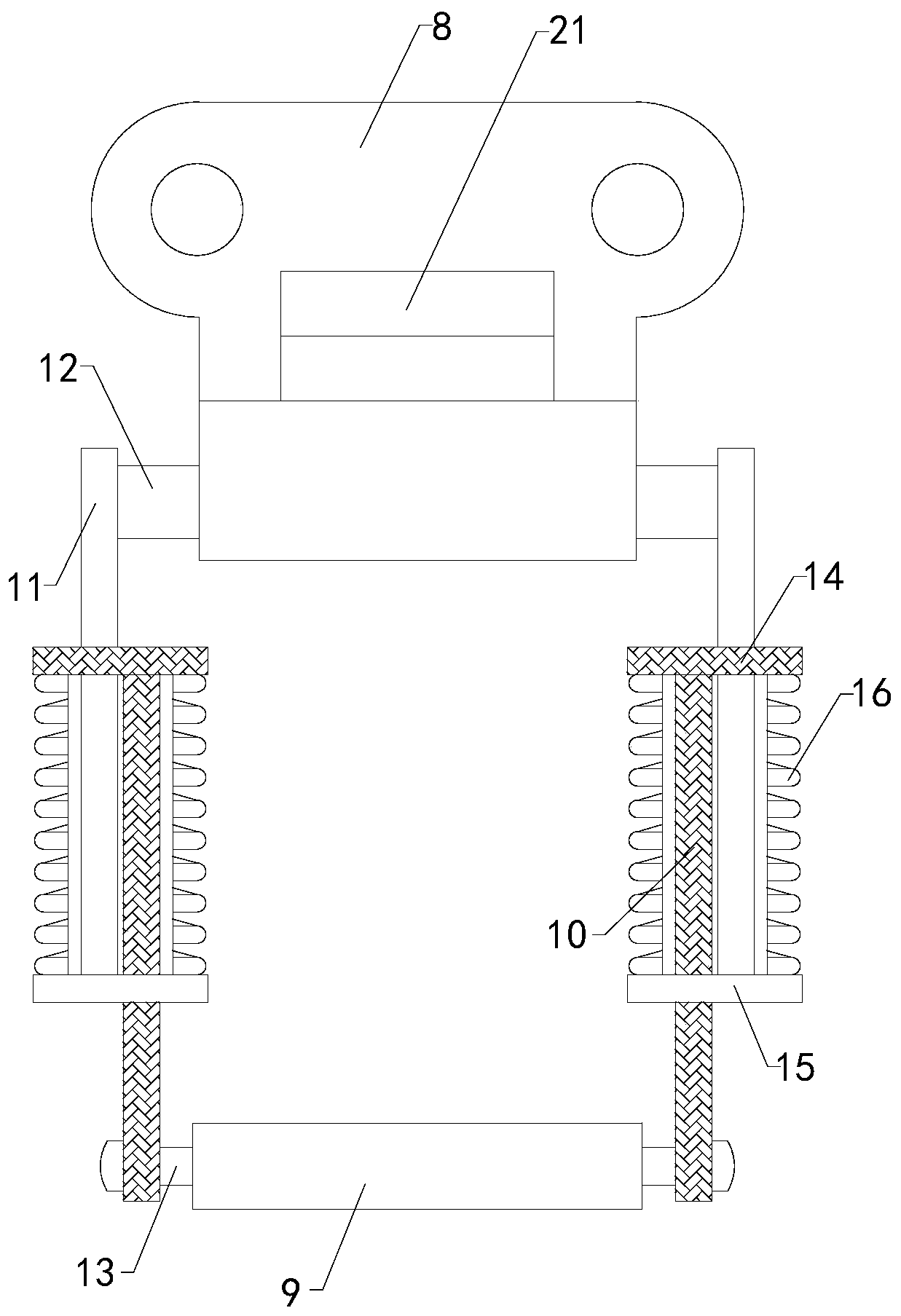
[0020] Reference Figure 1 to Figure 6 , A 3D printer wire winding mechanism of the present invention includes a core body 1, a through hole penetrating forward and backward is provided in the middle of the core body 1, and the outer front side and the rear side of the core body 1 are respectively fixedly sleeved with a left stop plate 2 and Right stop plate; The left stop plate 2 and the right stop plate have multiple sets of serrations 3 evenly arranged on the circumferential outer walls, and the tips of the multiple sets of serrations 3 diverge outward away from the central axis of the through hole; It includes an upper protective cover 4, a lower protective ...


PUM


Abstract

The invention belongs to the technical field of a wire rod, particularly relates to a 3D printer wire rod winding mechanism which can conveniently cut off the wire rod after being used, does not needmanual forcible pulling, reduces manpower and improves use reliability. After use, protection is facilitated, factors of reuse of damaged wires are reduced, the subsequent use utilization rate is increased, and use reliability is improved. The mechanism comprises a core body, wherein a through hole penetrating front and back is formed in the middle of the core body, a front side and a rear side ofthe exterior of the core body are fixedly sleeved with a left blocking disc and a right blocking disc correspondingly, a plurality of groups of sawteeth are circumferentially and uniformly distributed on circumferential outer walls of the left baffle disc and the right baffle disc, tip parts of a plurality of groups of sawteeth diverge outwards to be far away from the central axis of the throughhole, and an upper protective cover, a lower protective cover, a rotating shaft and a hasp device are further included, rear ends of the upper protective cover and the lower protective cover are rotatably connected, the rotating shaft is rotatably arranged in the through hole in a penetrating mode, and arc-shaped supporting grooves with the same radius as the rotating shaft are formed in the middles of a left side wall and a right side wall of the lower protective cover.

Description

Technical field [0001] The invention belongs to the technical field of wire materials, and particularly relates to a wire winding mechanism for a 3D printer. Background technique [0002] As we all know, the printer wire winding mechanism is an auxiliary device for winding wires so that people can better use the wire. It has been widely used in the field of wires; the existing wire winding device includes a core body and a core body. It has a cylindrical structure, with the axial direction of the core body as the front and back direction, the middle of the core body is provided with a through hole penetrating forward and backward, and the outer front side and the rear side of the core body are respectively fixedly sleeved with a left stop plate and a right stop plate; When the existing wire winding device is used, the produced wire is wound on the core body, and the left and right stop plates prevent the wire from sliding out on the core body. When used, the wire is pulled out an...

Claims


Application Information

Patent Timeline
Patent Type & Authority Applications(China)
IPC IPC(8): B65H75/32B65H75/14B65H75/18
CPCB65H75/14B65H75/18B65H75/32B65H2701/50
Inventor 周海鹏
Owner 盐城威布三维科技有限公司
Why Eureka
Try Eureka