Sewage treatment device capable of quantitatively collecting water quantity

A sewage treatment device, quantitative collection technology, applied in water/sewage treatment, water/sewage multi-stage treatment, water/sludge/sewage treatment, etc.

Inactive Publication Date: 2020-03-24
KEJIN INT (XIAN) ENVIRONMENTAL TECH CO LTD
View PDF1 Cites 5 Cited by
  • Summary
  • Abstract
  • Description
  • Claims
  • Application Information

AI Technical Summary

Problems solved by technology

[0004] The purpose of the present invention is to provide a sewage treatment device for quantitative collection of water volume, so as to solve the problem in the above-mentioned background technology that the volume of sewage water cannot be controlled, resulting in incomplete cleaning

Method used


Image

  • Sewage treatment device capable of quantitatively collecting water quantity
  • Sewage treatment device capable of quantitatively collecting water quantity
  • Sewage treatment device capable of quantitatively collecting water quantity

Examples


Embodiment 1

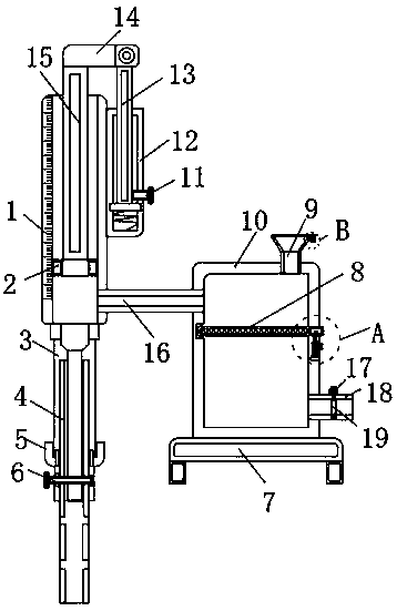
[0023] A sewage treatment device for quantitative collection of water, comprising a metering barrel 1, a second sliding rod 15 is inserted inside the metering barrel 1, and a connecting rod 14 is fixedly connected to the top of the second sliding rod 15, and the right side of the connecting rod 14 The first slide bar 13 is hinged, and the bottom end of the first slide bar 13 is inserted in the inside of the fixed block 12, the right side of the fixed block 12 is fixedly connected with the first push button 11, and the bottom ends of the second slide bar 15 are two The side is fixedly connected with a sealing ring 2, and the bottom end of the metering barrel 1 is fixed with a telescopic tube 3, and the inside of the telescopic tube 3 is inserted with a first connecting tube 4, and the inside of the first connecting tube 4 is inserted with a clamping shaft 6. The surface of a connecting pipe 4 is inserted with a rotary knob 5, and the right side of the bottom end of the metering ...

Embodiment 2

[0025] The inner wall of the metering barrel 1 is in conflict with the surface of the sealing ring 2, the sealing ring 2 and the metering barrel 1 form a telescopic structure, the sealing ring 2 is made of rubber, the surface of the sealing ring 2 is in conflict with the inner wall of the metering barrel 1, and the second slide bar 15 and the gap on the inner wall of the metering barrel 1 is sealed to prevent air leakage from causing insufficient suction when the second slide bar 15 is pulled. The block 12 forms a telescopic structure, and the bottom end of the first slide bar 13 is welded with a spring, and the bottom end of the spring is welded on the inner wall of the fixed block 12, and the first slide bar 13 is pushed upward to slide on the inner wall of the fixed block 12, and the fixed The spring at the bottom of the block 12 is stretched and deformed, and the movement of the second slide bar 15 generates suction to suck the sewage into the metering barrel 1. The surface...

Embodiment 3

[0027] The inside of the first connecting pipe 4 is in conflict with the surface of the clamping shaft 6, and the clamping shaft 6 and the first connecting tube 4 form an engaging structure, and the inside of the first connecting pipe 4 is in conflict with the surface of the clamping shaft 6, and the clamping shaft 6 and the The first connecting pipe 4 forms a snap-fit ​​structure, and the clamping shaft 6 is pulled out, so that the internal through hole of the first connecting pipe 4 can pass through normally. The telescopic tube 3 forms a rotating structure, the surface of the first connecting pipe 4 is fixed with an external thread, and the inner wall of the twist 5 is fixed with an internal thread, and the internal thread of the rotary 5 is used in conjunction with the external thread of the first connecting pipe 4. The rotation of the twist 5 moves the first connecting pipe 4, thereby adjusting the length of the first connecting pipe 4, thereby controlling the absorption o...


PUM


Abstract

The invention discloses a sewage treatment device capable of quantitatively collecting a water quantity. The sewage treatment device comprises a metering barrel, wherein a second sliding rod is inserted into the metering barrel; the top end of the second sliding rod is fixedly connected with a connecting rod; a first sliding rod is hinged at the right side of the connecting rod; the bottom end ofthe first sliding rod is inserted into a fixed block; a first push button is fixedly connected with and arranged at the right side of the fixed block; a sealing ring is fixedly connected with two sides of the bottom end of the second sliding rod; a telescopic pipe is fixedly arranged at the bottom end of the metering barrel; a first connecting pipe is inserted into the telescopic pipe; and a clamping shaft is inserted into the first connecting pipe. According to the invention, through arrangement of the metering barrel and the sealing ring, sewage is sucked upwards through ascending of the second sliding rod, and the position of a dial gauge on the surface of the metering barrel is observed through the second sliding rod in the suction process, so the suction amount of sewage is controlled; and through rotation of a rotary knob, the first connecting pipe moves in the telescopic pipe, so sewage at different depths can be sucked by the first connecting pipe.

Description

technical field [0001] The invention relates to the technical field of sewage treatment devices, in particular to a sewage treatment device for quantitatively collecting water. Background technique [0002] Sewage treatment is the process of purifying sewage to meet the water quality requirements of being discharged into a certain water body or reused. Sewage treatment is widely used in construction, agriculture, transportation, energy, petrochemical, environmental protection, urban landscape, medical treatment, catering, etc. field, and more and more into the daily life of ordinary people. [0003] For example, the national patent authorization announcement number: CN208414089U is a water surface floating sewage treatment device. This patent uses multiple filter layers and purification agents to filter and purify sewage, but if the mixing amount of sewage and purification agents cannot be controlled, there may be purification. Incomplete matter, so there is an urgent need ...

Claims


Application Information

Patent Timeline
Patent Type & Authority Applications(China)
IPC IPC(8): C02F9/04
CPCC02F1/00C02F1/001
Inventor 朱小捷
Owner KEJIN INT (XIAN) ENVIRONMENTAL TECH CO LTD
Why Eureka
Try Eureka