Thin adjusting gasket convenient to fix

A technology for adjusting gaskets and thin profiles, applied in the direction of washers, threaded fasteners, locking fasteners, etc., which can solve the problems of easy loosening of nuts, inability of gaskets to provide sufficient cushioning, and high hardness of gasket bodies. Avoid the effect of vibration loosening

Inactive Publication Date: 2020-03-24
WUXI JINZHONGYUAN MASCH CO LTD
View PDF10 Cites 1 Cited by
  • Summary
  • Abstract
  • Description
  • Claims
  • Application Information

AI Technical Summary

Problems solved by technology

[0003] In order to ensure the structural strength of the sheet, the gaskets in the prior art are all made of stronger materials, and the manufacturing process is also integrally formed, which makes the hardness of the gasket body relatively high. After the gasket is installed , if there is a large vibration when the equipment is working, the gasket cannot provide enough cushioning, so that the nuts cushioned by the gasket are easy to loosen, which needs to be improved

Method used


Image

  • Thin adjusting gasket convenient to fix
  • Thin adjusting gasket convenient to fix
  • Thin adjusting gasket convenient to fix

Examples


specific Embodiment approach 1

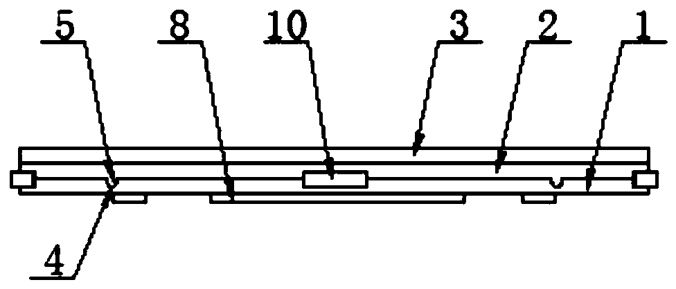
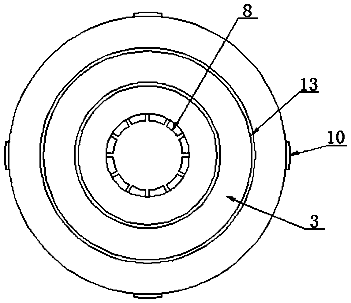
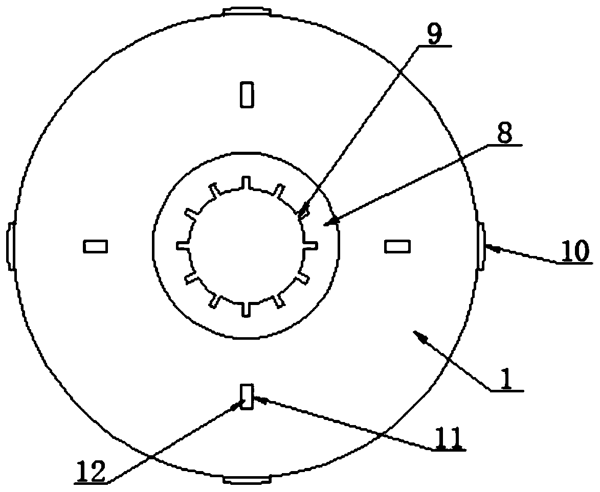
[0037] see as Figure 1-Figure 11 As shown, this specific embodiment includes No. 1 metal pad 1, No. 1 rubber pad 2, and No. 2 metal pad 3, wherein No. 1 metal pad 1, No. 1 rubber pad 2, and No. 2 metal pad 3 are stacked sequentially from bottom to top Setting; the upper surface of No. 1 metal pad 1 is provided with a limit groove 4, the inner end of the limit groove 4 is inserted on the inner side wall of the No. On the outer wall of the pad 1, the lower side wall of the No. 1 rubber pad 2 is integrally formed with a limit block 5, and the limit block 5 is movably fixed in the limit groove 4. The upper side of the outer wall of the No. 1 metal pad 1 The upper welding is provided with a limit plate 10, and the limit plate 10 is movably arranged on the outer wall of the No. 1 rubber pad 2. When the No. 1 metal pad 1 and No. 2 metal pad 3 squeeze the No. 1 rubber pad 2, the No. 1 rubber pad 2 Pad 2 deforms and overflows outward. At this time, the limit plate 10 is against the N...

specific Embodiment approach 2

[0045] see as Figure 12 to Figure 17 As shown, the difference between this specific embodiment and the specific embodiment one is: the rough pad 6 is replaced by a fixed ring 14, and a ring groove 18 is opened on the outer side of the lower side wall of the No. 2 metal pad 3 for fixing The ring 14 is movably arranged in the ring groove 18, the lower side wall of the No. 2 metal pad 3 is provided with a No. 1 card slot 16, and the outer end of the No. 1 card slot 16 is connected with the ring groove 18, and the No. 1 rubber pad 2 The upper side wall is provided with a No. 2 draw-in groove 17, and the inner side wall of the fixed ring 14 is welded with a clamp block 15. The upper side of the clamp block 15 is movable in the No. 1 draw-in slot 16. Limit movable card is located in No. two draw-in slot 17, after No. 1 rubber pad 2 is enclosed within on the bolt, at first put on fixed ring 14, then put on No. two metal pad 3, at this moment, No. 1 draw-in slot 16, The second slot ...


PUM


Abstract

The invention relates to the technical field of metal gaskets, in particular to a thin adjusting gasket convenient to fix. A first metal gasket, a first rubber gasket and a second metal gasket are sequentially stacked from bottom to top; a limiting groove is formed in the upper surface of the first metal gasket, the inner end of the limiting groove is arranged on the inner side wall of the first metal gasket in a penetrating mode, the outer end of the limiting groove is arranged on the outer side wall of the first metal gasket in a penetrating mode, and a limiting block is fixedly arranged onthe lower side wall of the first rubber gasket and movably clamped in the limiting groove; a rough gasket is fixedly arranged on the lower side wall of the second metal gasket and abuts against the upper surface of the first rubber gasket; the first rubber gasket is clamped between the first metal gasket and the second metal gasket, the first rubber gasket and the first metal gasket are connectedthrough the limiting groove and the limiting block, and the first rubber gasket and the second metal gasket are connected through the rough gasket. Therefore, when the nut is screwed, elastic extrusion exists in the gasket, and the nut is jacked tightly and is not prone to loosening.

Description

technical field [0001] The invention relates to the technical field of metal shims, in particular to a thin adjustment shim that is easy to fix. Background technique [0002] Gaskets are mainly used in the structure of bolts and nuts. They are placed between the nuts and the base plate of the equipment to fill the loose gaps when the nuts cannot be tightened. [0003] In order to ensure the structural strength of the sheet, the gaskets in the prior art are all made of stronger materials, and the manufacturing process is also integrally formed, which makes the hardness of the gasket body relatively high. After the gasket is installed , if the equipment generates a large vibration during operation, the gasket cannot provide enough cushioning, so that the nuts cushioned by the gasket are easy to loosen, which needs to be improved. Contents of the invention [0004] The object of the present invention is to aim at the defects and deficiencies of the prior art, and provide a t...

Claims


Application Information

Patent Timeline
Patent Type & Authority Applications(China)
IPC IPC(8): F16B39/24F16B43/00
CPCF16B39/24F16B43/00
Inventor 谢中方
Owner WUXI JINZHONGYUAN MASCH CO LTD
Why Eureka
Try Eureka