
A method for positioning the anatomical insertion point of the medial patellar ligament

A positioning method and positioning method technology, applied in stereotaxic surgical instruments, medical science, surgery, etc., to achieve the effects of improving surgical wounds, eliminating radiation effects, and reducing surgical scars

Active Publication Date: 2022-06-14
THE SECOND PEOPLES HOSPITAL OF SHENZHEN
View PDF0 Cites 0 Cited by
  • Summary
  • Abstract
  • Description
  • Claims
  • Application Information

AI Technical Summary

Problems solved by technology

However, domestic and foreign scholars have found in long-term follow-up that there are still obvious recovery problems in the postoperative period, such as unexplained knee swelling and pain, limited flexion, difficulty in recovering to the level of healthy knee movement, scar hyperplasia, traumatic arthritis, etc.
The determination of the position of the femoral lateral insertion of the medial patellofemoral ligament is a crucial factor for the success of the operation. Traditional knee arthroscopic surgery often requires repeated fluoroscopy with the help of an intraoperative C-arm machine to find the surgical entry point closest to the anatomical position, or In order to improve the probability of finding the insertion point at one time, a larger incision is assisted, but the above measures are also likely to cause complications such as subcutaneous hyperplasia, adhesion, muscle damage, and nerve damage, all of which are related to excessively large surgical wounds.
However, based on the existing technical conditions, it is difficult to directly and accurately find the insertion point of the medial patellofemoral ligament on the femoral side under arthroscopy, which makes minimally invasive arthroscopic surgery take longer, and the probability of secondary complications after surgery is high

Method used


Image

  • A method for positioning the anatomical insertion point of the medial patellar ligament
  • A method for positioning the anatomical insertion point of the medial patellar ligament
  • A method for positioning the anatomical insertion point of the medial patellar ligament

Examples


specific Embodiment

specific embodiment

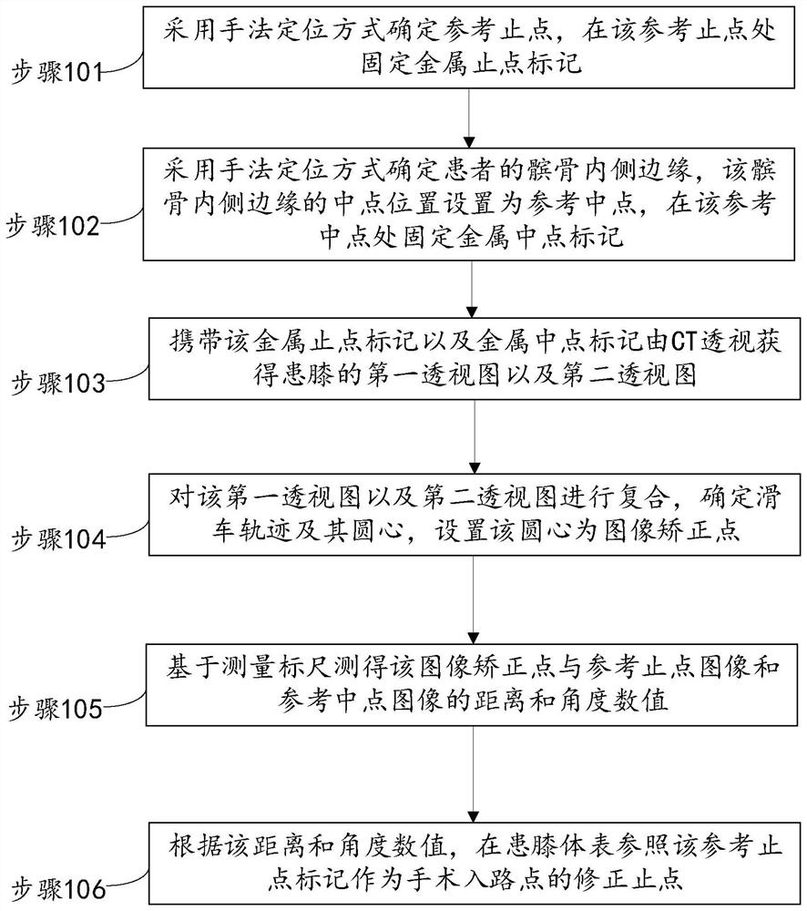
[0050] Please refer to figure 1 , the anatomical insertion point positioning method of the medial patellar ligament of the present embodiment mainly comprises the following steps:

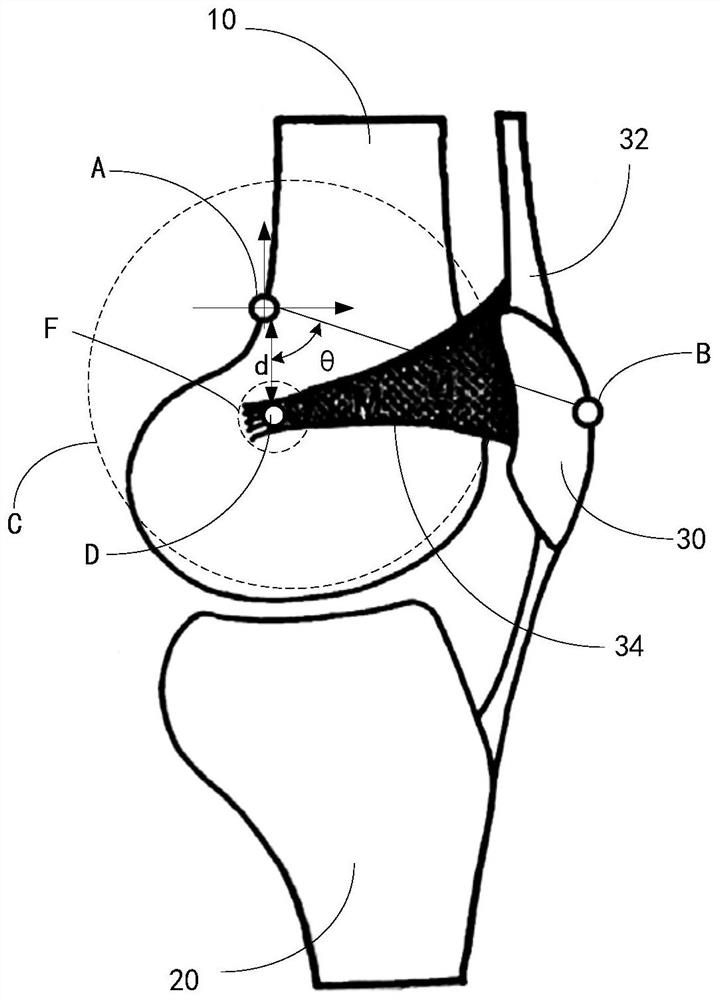
[0051] Step 101: Determine the reference dead point A by manual positioning, and fix the metal dead point mark at the reference dead point A;

[0052] Step 102: Determine the inner edge of the patient's patella 30 by manual positioning, set the midpoint position of the inner edge of the patella 30 as a reference midpoint B, and fix a metal midpoint marker at the reference midpoint B;

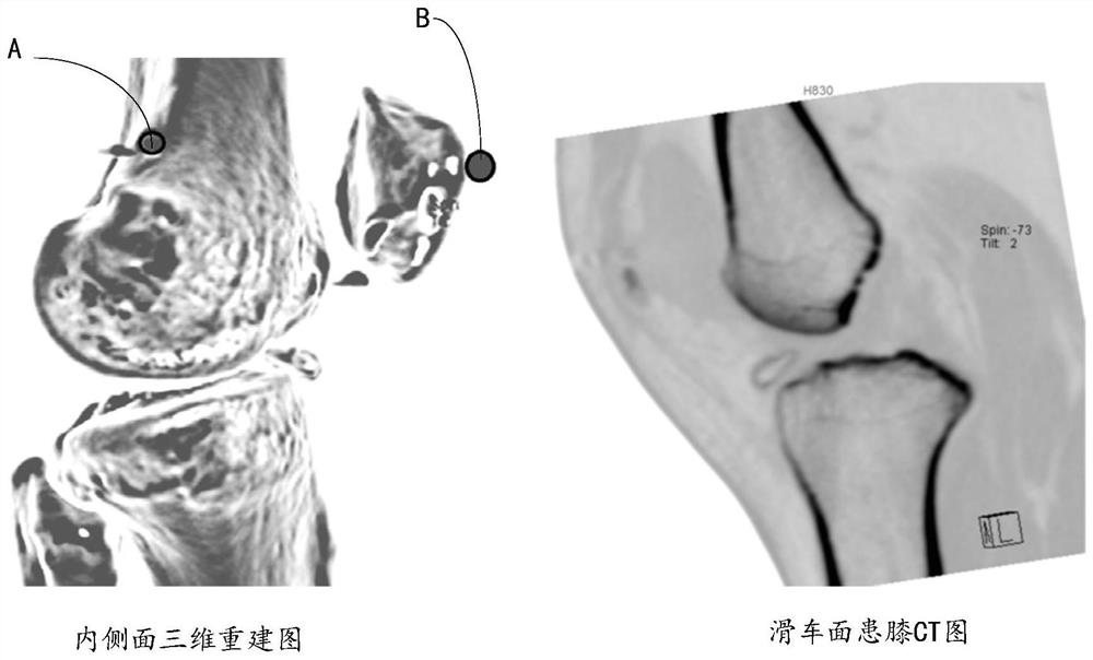
[0053] Step 103: Obtain the first perspective view and the second perspective view of the affected knee through CT fluoroscopy with the metal stop mark and the metal midpoint mark;

[0054] Step 104: Composite the first perspective view and the second perspective view, determine the track C of the pulley and its rotation center, and set the rotation center as the image correction point;

[005...


PUM


Abstract

The present application discloses a method for positioning the anatomical insertion point of the medial patellar ligament, comprising the following steps: determining the reference insertion point by means of manual positioning, fixing a metal insertion point mark at the reference insertion point; determining the reference midpoint by means of manual positioning, Fix the metal midpoint mark at the reference midpoint; carry the metal end point mark and the metal midpoint mark to obtain the first perspective view and the second perspective view of the affected knee from CT perspective; for the first perspective view and the second perspective view Composite the figure, determine the track of the pulley and its center of rotation, set the center of rotation as the image correction point; measure the distance and angle value between the image correction point and the reference end point image and the reference midpoint image based on the measurement scale; according to the distance and Angle value, refer to the reference insertion point mark on the body surface of the affected knee as the modified insertion point of the surgical approach point. With the help of the method of the present application, customized surgical approaches can be provided for patients, the incidence of postoperative complications can be reduced, and the operation time can be shortened.

Description

technical field [0001] The present application relates to the technical field of medical image processing, in particular to a method for positioning the anatomical insertion point of the medial patellar ligament. Background technique [0002] The knee joint is a synovial joint composed of the distal femur, proximal tibia, and patella. Patients suffering from sports accidents or direct violence often result in rupture of the medial patellofemoral ligament of the knee, which requires knee arthroscopic surgery to complete ligament reconstruction. [0003] Knee arthroscopic surgery requires two surgical incisions. The arthroscopic metal tube with lighting device is inserted into the joint cavity through the surgical incision, and the internal structure of the joint cavity is enlarged on the monitor to observe the pathological changes in the joint cavity. Doctors can confirm the cause of pain or find other lesions through arthroscopy and treat them accordingly. [0004] Common ...

Claims


Application Information

Patent Timeline
Patent Type & Authority Patents(China)
IPC IPC(8): A61B34/20A61B90/11
CPCA61B34/20A61B90/11A61B2034/2065
Inventor 苏帆朱伟民
Owner THE SECOND PEOPLES HOSPITAL OF SHENZHEN
Learn More