Check patentability & draft patents in minutes with Patsnap Eureka AI!

Power flow control device for controlling the distribution of currents in a mesh network

A technology for controlling equipment and power flow. It is applied in the circuit layout of AC and DC networks, load balancing in DC networks, and circuit devices in DC networks. It can solve complex problems and achieve the effect of minimizing losses.

Active Publication Date: 2020-03-24
SUPERGRID INSTITUTE SAS +1
View PDF11 Cites 0 Cited by
  • Summary
  • Abstract
  • Description
  • Claims
  • Application Information

AI Technical Summary

Benefits of technology

The technical effect of this patented method helps reduce power loss by distributing it over multiple networks equally well.

Problems solved by technology

Technological Problem addressed in this patented technical problem relates to improving the performance and functionality of electric grids used on highways. Current methods involve creating connections within the wires themselves but there may be some disruptions caused during normal operations due to factors like electrical noise. These techniques include adjustment of voltage levels along the entire length of the circuit, addition of inductors or resistive elements, insertion of voltage sources into existing circuits, etc., while others aimed towards enhancing the overall function of electric Grounds over long distances.

Method used


Image

  • Power flow control device for controlling the distribution of currents in a mesh network
  • Power flow control device for controlling the distribution of currents in a mesh network
  • Power flow control device for controlling the distribution of currents in a mesh network

Examples


Embodiment Construction

[0087] The power flow control device of the invention is intended for use in grid networks of preferably high voltage direct current. Depending on its configuration, it can also be used in AC grid networks. As will be seen hereinafter, this may be the case when the switching arrangement comprises current and voltage reversible power switches.

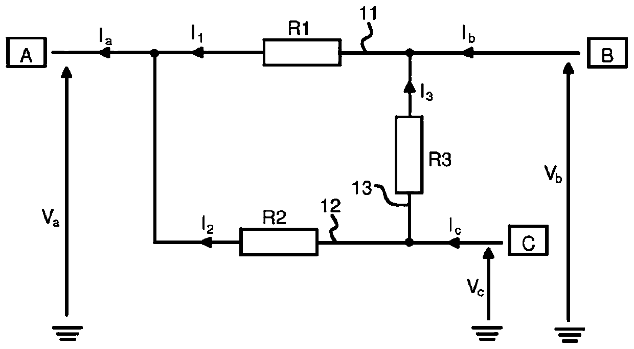
[0088] as combined above figure 1 As mentioned, a mesh network is most simply in the form of three interconnected nodes.

[0089] Each node is advantageously directly or indirectly connected to one or several switching stations. Switching station A is thus connected to the first node. Switching station B is thus connected to the second node of the network. The switching station C is thus connected to the third node of the network.

[0090] Each switching station is intended to inject power into or extract power from the network.

[0091] Each switching station is designed to inject current into the network or extract current from ...


PUM


Abstract

The invention concerns a power flow control device intended to be used in a mesh network, said device comprising: a first voltage source connected between the first terminal (B1) of same and the thirdterminal (B3) of same, a second voltage source connected between the second terminal (B2) of same and the third terminal (B3) of same, a current source connected alternately to the first voltage source and the second voltage source and configured to ensure a transfer of energy between the first voltage source and the second voltage source, switching means arranged to allow said current source tobe connected alternately in parallel with the first voltage source or in parallel with the second current source.

Description


Claims


Application Information

Patent Timeline
Owner SUPERGRID INSTITUTE SAS
Features
  • R&D
  • Intellectual Property
  • Life Sciences
  • Materials
  • Tech Scout
  • Unparalleled Data Quality
  • Higher Quality Content
  • 60% Fewer Hallucinations
Learn More