

Clamping and fixing device for mechanical accessory production
A technology of clamping and fixing, mechanical accessories, applied in the direction of spraying devices, etc., can solve the problems of affecting the production efficiency of side cover plates, easy to shake, etc., and achieve the effect of improving convenience and stability, improving stability, and avoiding paint entry
- Summary
- Abstract
- Description
- Claims
- Application Information
AI Technical Summary
Problems solved by technology
Method used
Image

Examples
Embodiment 1
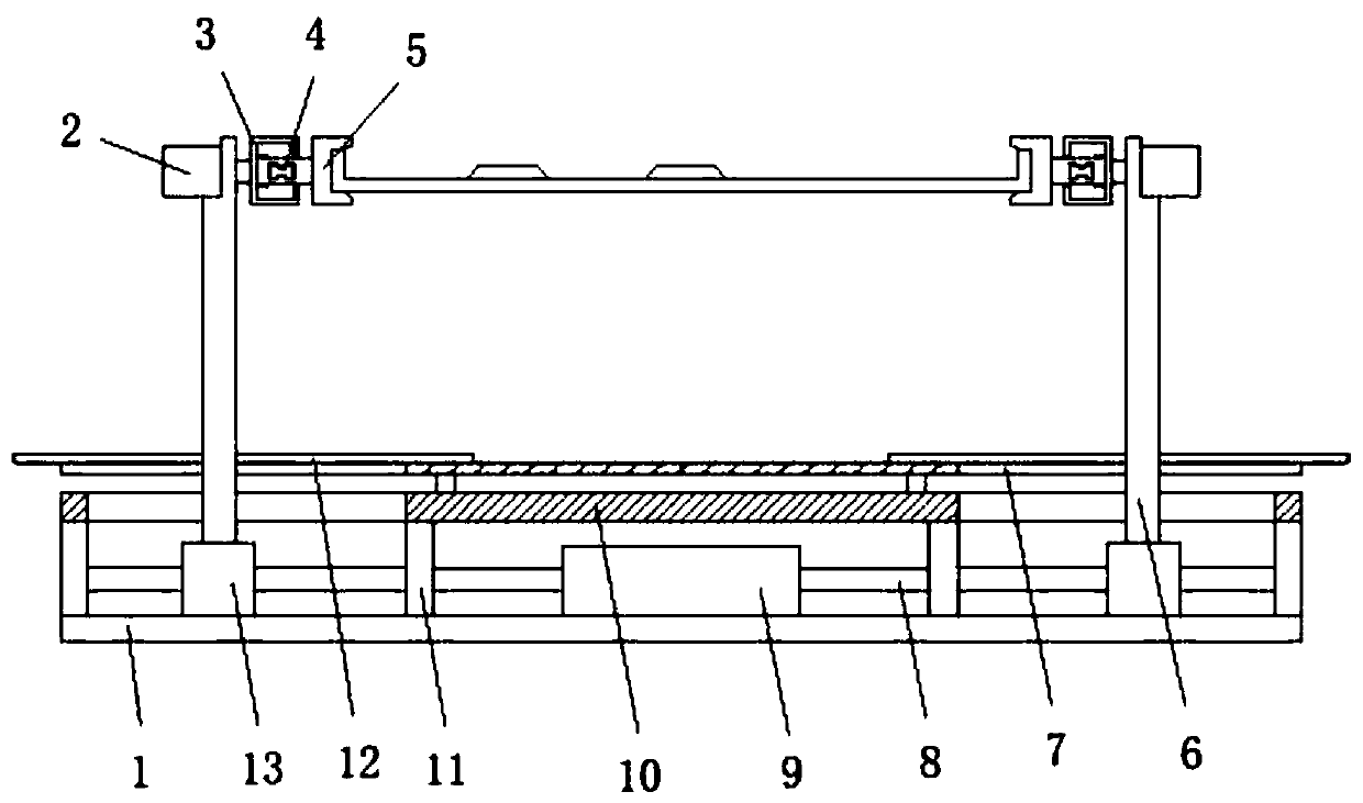
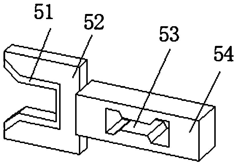
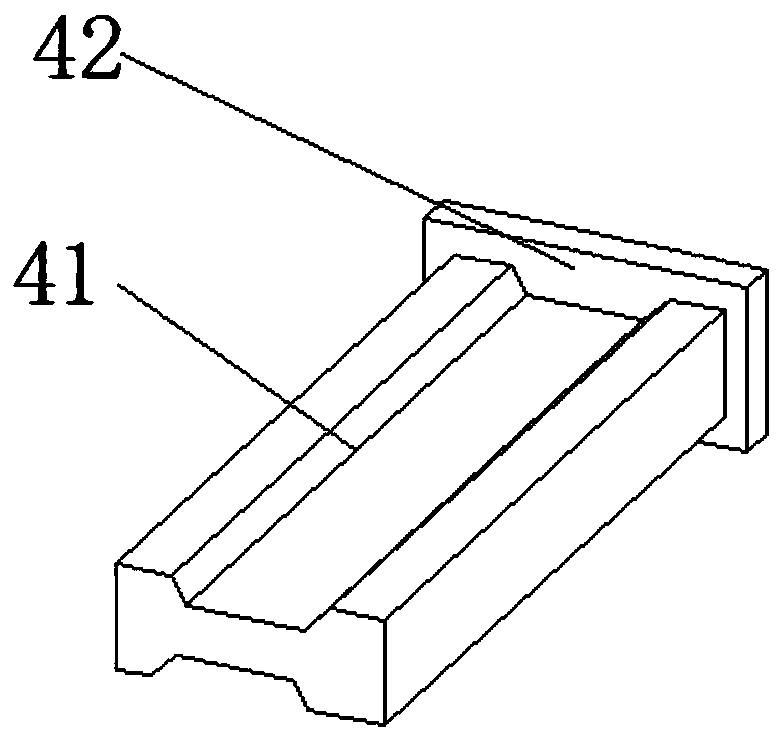
[0029] refer to Figure 1-4 , a clamping and fixing device for the production of mechanical parts, including a base plate 1, a plurality of partitions 11 are fixedly installed on the top of the base plate 1, and a top plate 10 is fixedly installed between the tops of the partitions 11, and the top of the top plate 10 is two Both ends are provided with strip-shaped through holes, and the insides of the two strip-shaped through holes are slidably connected with support rods 6, and the bottom ends of the two support rods 6 are equipped with driving mechanisms. Stepper motors 2 are fixedly installed, and the ends of the output shafts of the two stepper motors 2 are fixedly installed with supporting mechanisms 3, and the sides of the supporting mechanisms 3 are fixedly installed with a plurality of clamping mechanisms 5. When the side cover is fixed, the side cover is placed between the two support mechanisms 3, and the drive mechanism is used to drive the two support rods 6 to app...
Embodiment 2
[0036] refer to Figure 1-5, a clamping and fixing device for the production of mechanical parts, the top of the top plate 10 is fixed with two lower baffles 7 by Velcro, and the top side of the lower baffle 7 is provided with a gap matching the strip-shaped through hole.
[0037] Upper baffles 12 are fixedly mounted on both sides of the support rod 6 , and the bottom of the upper baffle 12 is slidably connected to the lower baffle 7 .
[0038] In this embodiment, a lower baffle 7 and an upper baffle 12 that are easy to disassemble are installed on the top of the device. During the movement of the support rod 6, the upper baffle 12 slides above the lower top plate 7, and then the gap at the top of the device is closed. Blocking is carried out to prevent the paint from entering the interior of the device during the paint spraying process, causing damage to the device and prolonging the service life of the device.
PUM
 Abstract
Description
Claims
Application Information