
Efficient clamp capable of automatically clamping and grinding eccentric parts

A clamping and grinding technology, applied in the direction of grinding workpiece supports, can solve the problems of error, large center deviation, manual clamping error, etc., and achieve the effect of saving labor costs and improving the efficiency of clamping

Pending Publication Date: 2020-03-27
广东豪特曼机床股份有限公司
View PDF0 Cites 0 Cited by
  • Summary
  • Abstract
  • Description
  • Claims
  • Application Information

AI Technical Summary

Problems solved by technology

[0002] The fixture of the grinding machine is used to clamp the workpiece, and the tool and the workpiece on the grinding machine are used for grinding. However, the traditional grinding machine fixture usually has the following defects: (1) most of the fixtures are based on the center, and the clamped workpiece is It needs to be consistent with the center of the spindle before grinding can be carried out; (2) Workers need to operate the fixture to manually clamp the workpiece, and the strength of different people is different, resulting in manual clamping errors; (3) It is necessary to pass the Manual operation to find the center of the fixture for manual clamping, the center deviation is large, which will bring errors

Method used


Image

  • Efficient clamp capable of automatically clamping and grinding eccentric parts
  • Efficient clamp capable of automatically clamping and grinding eccentric parts

Examples


Embodiment Construction

[0015] The present invention will be further described below in conjunction with accompanying drawing:

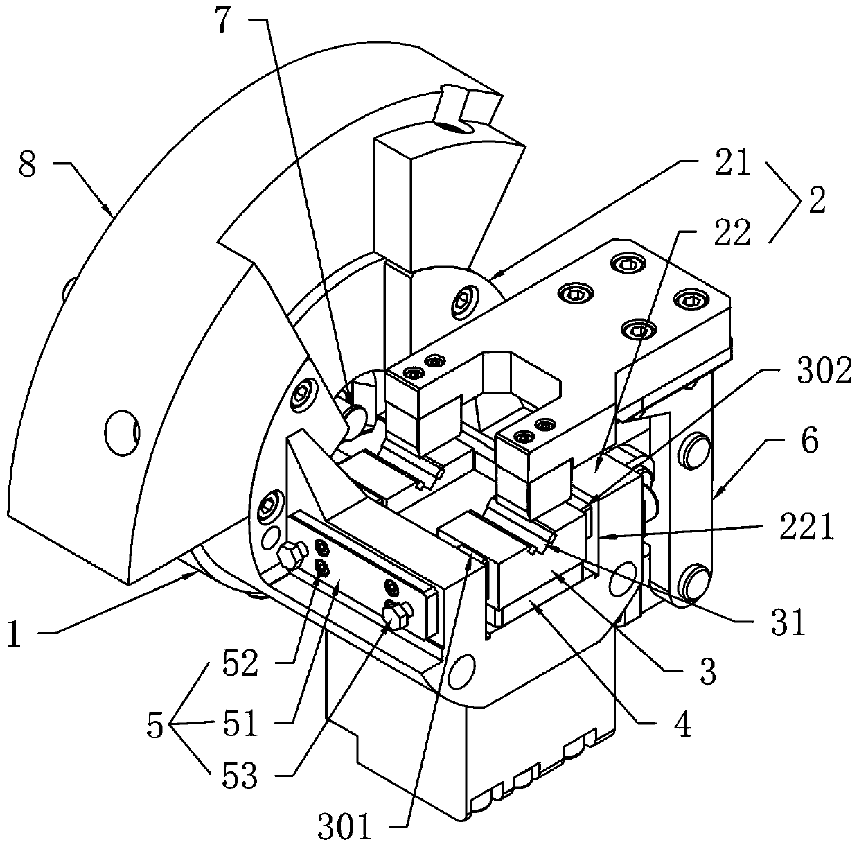
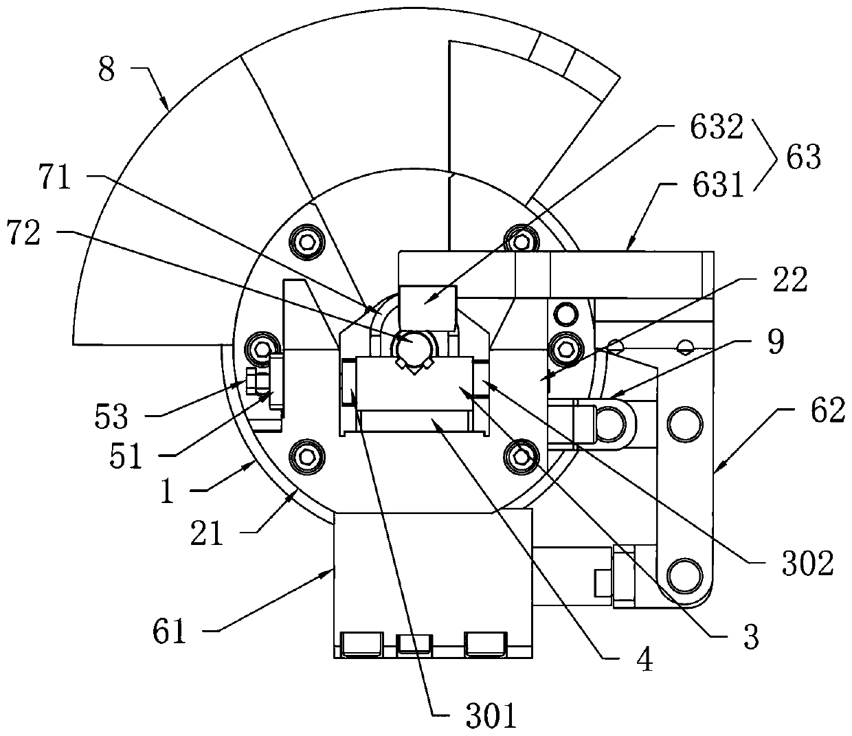
[0016] Such as Figure 1-2 As shown, a high-efficiency fixture that can automatically clamp and grind eccentric parts includes a flange 1, a clamp seat 2, a support block 3, a lower backing plate 4, a side clamping assembly 5, a top pressing assembly 6, a top Tail assembly 7 and counterweight 8; said clamp seat 2 includes a disc 21 fixed on the front side of the flange 1 and a mounting seat 22 fixed on the front side of the disc 21; said mounting seat 22 is provided with a The mounting grooves 221 on the front and rear sides; the bottom backing plate 4 is fixed on the bottom of the mounting groove 221; the surface of the support block 3 is provided with a placement groove 31; the left and right backing plates are respectively fixed on the left and right sides of the support block 3 301 and the right backing plate 302; the support block 3 is placed above the lower backing p...


PUM


Abstract

The invention provides an efficient clamp capable of automatically clamping and grinding eccentric parts. The clamp comprises a flange plate, a clamping base, a supporting block, a lower backing plate, a side clamping assembly, a top pressing assembly, a top tail assembly and a balancing weight, wherein the clamping base comprises a disc fixed on the front side of the flange plate and a mounting seat fixed on the front side of the disc, a mounting groove penetrating through the front side and the rear side of the mounting base is formed on the mounting base, the lower backing plate is fixed atthe bottom in the mounting groove, placing grooves are formed on surfaces of the supporting block, a left backing plate and a right backing plate are respectively fixed on left and right sides of thesupporting block, the supporting block is placed above the lower backing plate, the right backing plate contacts with an inner wall of the mounting groove, a lateral clamping assembly is used for laterally pressing the supporting block, the top pressing assembly is used for pressing a workpiece, the top tail assembly is mounted in the center of the disc, and the balancing weight is fixed to the periphery of the disc and located on the side opposite to the top pressing assembly. The clamp is advantaged in that the clamp is capable of installing eccentric workpieces and convenient to install.

Description

technical field [0001] The invention relates to the technical field of grinding machines, in particular to a high-efficiency fixture capable of automatically clamping and grinding eccentric parts. Background technique [0002] The fixture of the grinding machine is used to clamp the workpiece, and the tool and the workpiece on the grinding machine are used for grinding. However, the traditional grinding machine fixture usually has the following defects: (1) most of the fixtures are based on the center, and the clamped workpiece is It needs to be consistent with the center of the spindle before grinding can be carried out; (2) Workers need to operate the fixture to manually clamp the workpiece, and the strength of different people is different, resulting in manual clamping errors; (3) It is necessary to pass the Manually find the center of the fixture for manual clamping, and the center deviation is large, which will cause errors. [0003] Therefore also need to improve. C...

Claims


Application Information

Patent Timeline
Patent Type & Authority Applications(China)
IPC IPC(8): B24B41/06
CPCB24B41/062
Inventor 曾俊刘太明
Owner 广东豪特曼机床股份有限公司
Learn More