
Electromagnetic needle lifting unit applied to electronic jacquard machine, electromagnetic needle lifting module

An electronic jacquard and electromagnetic technology, applied in jacquard machines, textiles, textiles and papermaking, etc., can solve the problems of impact wear, manufacturing difficulties, fatigue fracture, etc., to eliminate fatigue wear and fracture, low sealing requirements, The effect of low part wear

Inactive Publication Date: 2020-03-27
SHAOXING JIABAO TEXTILE MACHINERY TECH
View PDF8 Cites 0 Cited by
  • Summary
  • Abstract
  • Description
  • Claims
  • Application Information

AI Technical Summary

Problems solved by technology

[0006] From the above analysis, it can be seen that the principle and structure are relatively complicated. For example, the shape of the above-mentioned swing hook is tortuous and changeable, the booster piece of the above-mentioned sliding hook is complicated, which leads to difficulties in manufacturing, and the installation of the swing hook and the above-mentioned pressure spring is inefficient and time-consuming. The following technical deficiencies:
[0007] Many moving parts inside the above-mentioned needle lifting assembly (such as the above-mentioned fulcrum shaft, the above-mentioned booster plate, etc.) need to be manually lubricated with grease. When the grease is stained with flying flowers and other debris, the lubrication effect will be affected, so the needle lifting assembly requires high sealing performance. , and under the condition of high speed, high temperature and low heat dissipation, the fulcrum shaft is still easy to wear
[0008] When the needle lifting assembly is running at high speed, the above-mentioned electromagnet has high requirements for heat dissipation, otherwise the electromagnet is easily damaged, and there is a dilemma that it is difficult to balance heat dissipation and sealing
[0009] The suction method of the above-mentioned suction head and the inner surface of the upper end of the swing hook is a rigid, high-frequency percussion type suction, which is prone to impact wear. After wear, it will cause weaving due to the failure of the swing hook to be effectively attracted. fabric defect
[0010] The booster piece of the sliding hook is prone to fatigue fracture under high-frequency working conditions: the booster piece of the sliding hook is “forced” to deform at high frequency when the sliding hook is hooked and disengaged, and the elastic deformation of the booster piece is accelerated after fatigue damage. Weak, or even broken, so the booster is usually a "weak structural part". Production practice also found that: the low temperature of the booster leads to elastic attenuation, which affects its normal performance. The weak elasticity of the sheet leads to large-scale occurrence of "multiple" weaving defects (not normally interwoven) in the fabric
[0011] The longitudinal size of the entire needle lifting assembly is relatively large (viewed from the perspective of the front and rear sheds), which correspondingly leads to a large longitudinal size of the jacquard machine with a fixed number of needles, which is not conducive to the manufacture of jacquard machines with large or super large number of needles, and affects the effective space of the whole machine. Utilization: the compression spring occupies the longitudinal space for installing the needle lifting assembly, the sliding hook is installed in a curved sliding manner, and the hook-hook joint structure leads to the space required for the large swing movement of the swing hook. The hook needs to have a shaft hole and a convex arc-shaped contact surface. These structures occupy a large amount of the actual comprehensive space of the needle lifter assembly.

Method used


Image

  • Electromagnetic needle lifting unit applied to electronic jacquard machine, electromagnetic needle lifting module
  • Electromagnetic needle lifting unit applied to electronic jacquard machine, electromagnetic needle lifting module
  • Electromagnetic needle lifting unit applied to electronic jacquard machine, electromagnetic needle lifting module

Examples


Embodiment Construction

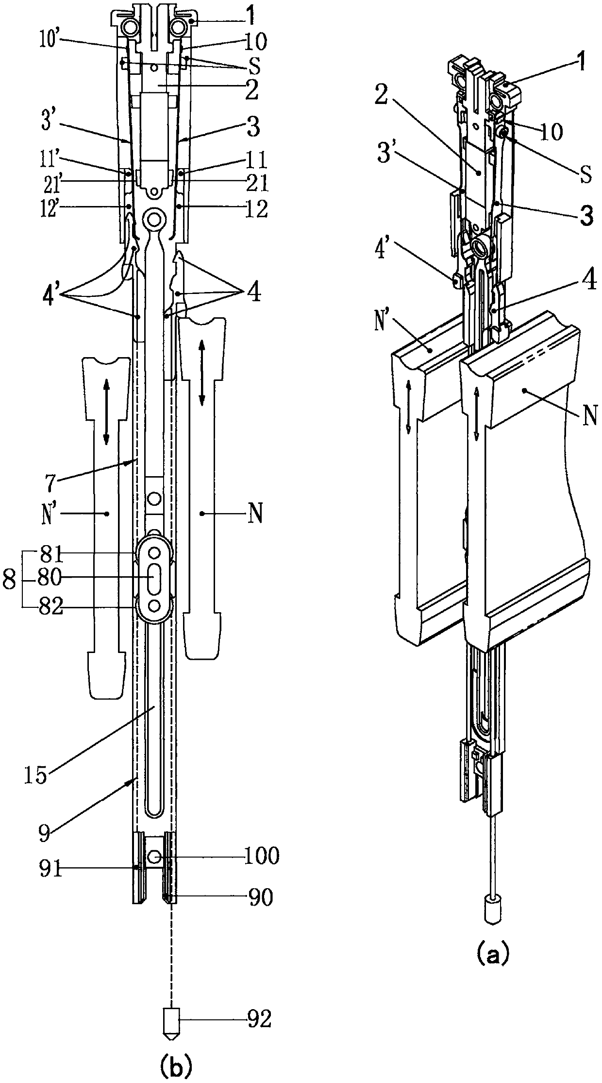
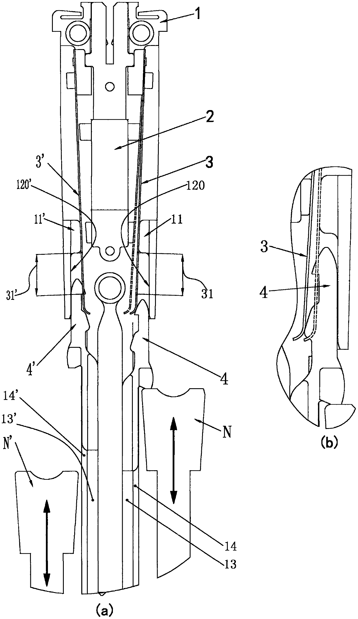
[0037] Please refer to the attached Figure 1~6 As shown, the electromagnetic needle lifting unit used for electronic jacquard machines is mainly composed of a base plate 1, an electromagnet 2 fixed on the base plate 1, a sliding hook 4, a sliding hook 4' and a rope-connected pulley block. The sliding hook 4 includes The hook body part 5 and the rod body part 6, the sliding hook 4' includes the hook body part 5' and the rod body part 6', the head end of the hook body part 5 forms a hook head 51, and the head end of the hook body part 5' forms a hook head 51', the bottom surface 5b of the hook body part 5 and the bottom surface 5b' of the hook body part 5' are respectively used as thrust surfaces for the lifting knives N and N' that move up and down alternately, and the rod body parts 6 and 6' slide vertically respectively It is installed on the base plate 1 , and the hook head 51 corresponds to the hook head 51 ′.

[0038] Wherein, the rope-connected pulley block is a known s...


PUM


Abstract

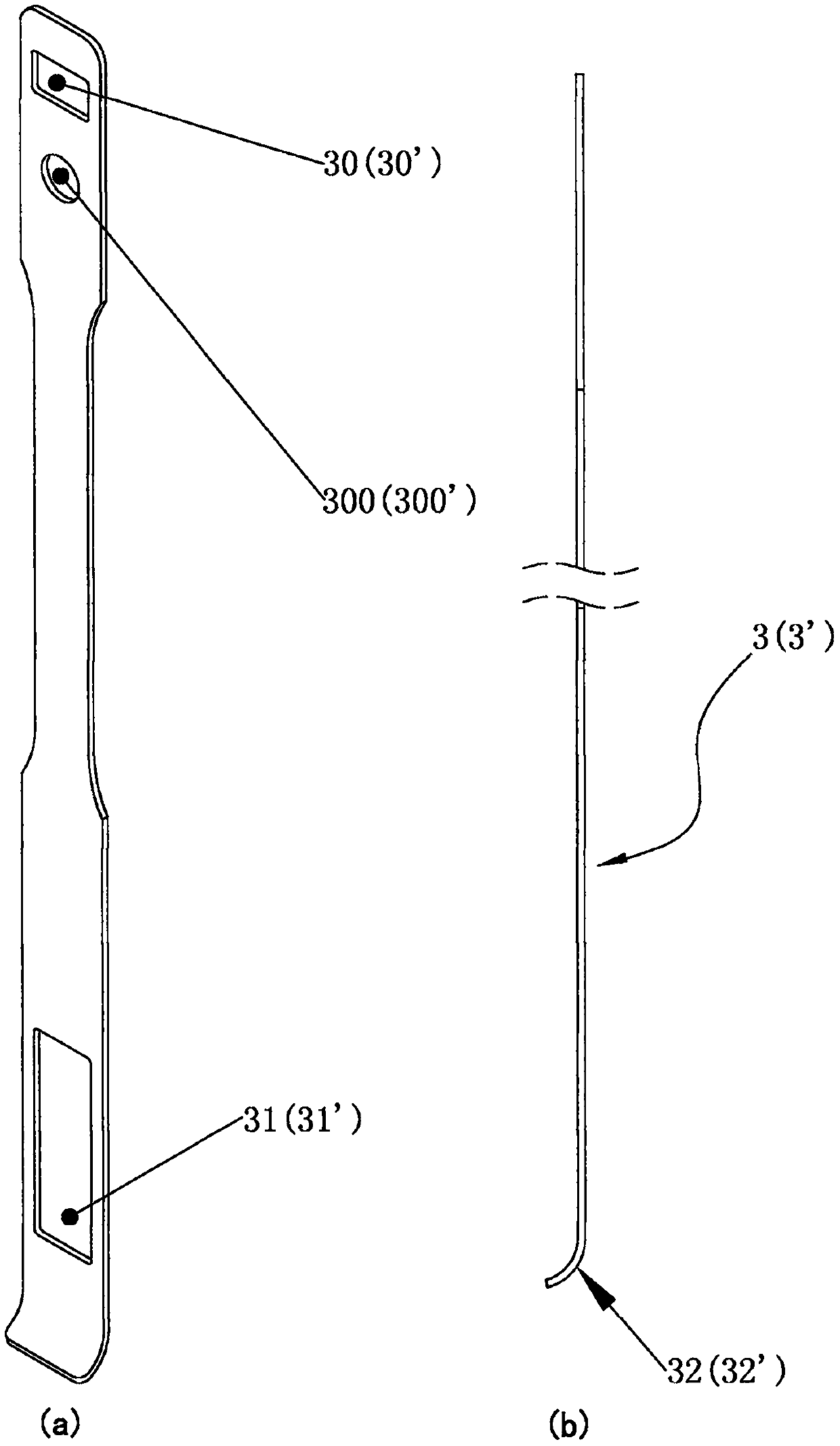
The invention discloses an electromagnetic needle lifting unit applied to an electronic jacquard machine, and an electromagnetic needle lifting module. The electromagnetic needle lifting unit comprises a substrate, an electromagnet, two sliding hooks and two flexible reeds correspondingly positioned and fixed on the substrate, wherein each of the two sliding hooks comprises a rod body part and a hook body part; hook heads are correspondingly arranged at the head ends of the two hook body parts; bottom surfaces of the two hook body parts are correspondingly formed into bearing surfaces; the tworod body parts are correspondingly vertically installed on the substrate in a sliding manner; the two hook heads are corresponding to each other; each flexible reed stretching into a sliding chute ofthe corresponding hook body part and leaning against the sliding chute with the aid of a limiting body is provided with a hanging hole and a bent curve bent towards the electromagnet; the hook head and the hook body part of each sliding hook are correspondingly provided with a first curve and a second curve that can rigidly conflict with the corresponding flexible reed, and the second curve is further away from the axis of the hook body part than the first curve; and the back sliding surface of each hook body part is in vertical surface slide fitting with the lateral inner wall of the slidingchute of the corresponding hook body part. The unit is good in durability and high in movement reliability; and the module formed by fixing the units with two end cover plates is low in sealing requirement, free from sliding and small in longitudinal size.

Description

【Technical field】 [0001] The invention relates to an electromagnetic needle lifting unit for an electronic jacquard machine and an assembly of the electromagnetic needle lifting unit, belonging to the technical field of the electronic jacquard machine. 【Background technique】 [0002] At present, the needle lifting components used in electronic jacquard machines at home and abroad generally have the following principles and structures: Figure 8 , 9 , 10, the upper end of the swing hook is attracted and disengaged through the magnetization and demagnetization of the electromagnet 2, and the reciprocating swing of the swing hook is generated, thereby realizing the hooking, fixing and releasing of the sliding hook at the lower end of the swing hook hook up. The assembly of each needle lifting unit of the needle lifting assembly is as follows: [0003] Electromagnet 2, compression spring K', compression spring K, fixed seat 91 and rope guide seat 90 are all installed on the pa...

Claims


Application Information

Patent Timeline
Patent Type & Authority Applications(China)
IPC IPC(8): D03C3/24D03C3/26
CPCD03C3/24D03C3/26
Inventor 张军波
Owner SHAOXING JIABAO TEXTILE MACHINERY TECH
Learn More