Yarn spinning tensioning device

A tensioning device and yarn technology, which is applied in textiles, textiles, papermaking, looms, etc., can solve problems such as long yarn delivery path, affecting operation, and yarn knotting

Active Publication Date: 2020-03-27
安徽金弘润新材料科技有限公司
View PDF8 Cites 7 Cited by
  • Summary
  • Abstract
  • Description
  • Claims
  • Application Information

AI Technical Summary

Problems solved by technology

[0003] 1. After the yarn is pulled, it will drive the yarn bobbin to rotate synchronously at a high speed. When the yarn is under the traction force and disappears, the yarn bobbin still rotates for a while under the action of inertia, so that the unwinding yarn is not in a tensioned state at this time. , the untightened yarn is prone to yarn knotting after being subjected to the traction force for the second time, which will affect the subsequent operation; 2. Due to the long delivery path of the yarn, the yarn in the middle will also appear due to the influence of its own gravity more relaxed situation

Method used


Image

  • Yarn spinning tensioning device
  • Yarn spinning tensioning device
  • Yarn spinning tensioning device

Examples


Embodiment Construction

[0028] Embodiments of the present invention will be described below with reference to the drawings. In the process, in order to ensure the clarity and convenience of illustration, we may exaggerate the width of the lines or the size of the constituent elements in the diagram.

[0029] In addition, the following terms are defined based on the functions in the present invention, and may be different according to the user's or operator's intention or practice. Therefore, these terms are defined based on the entire content of this specification.

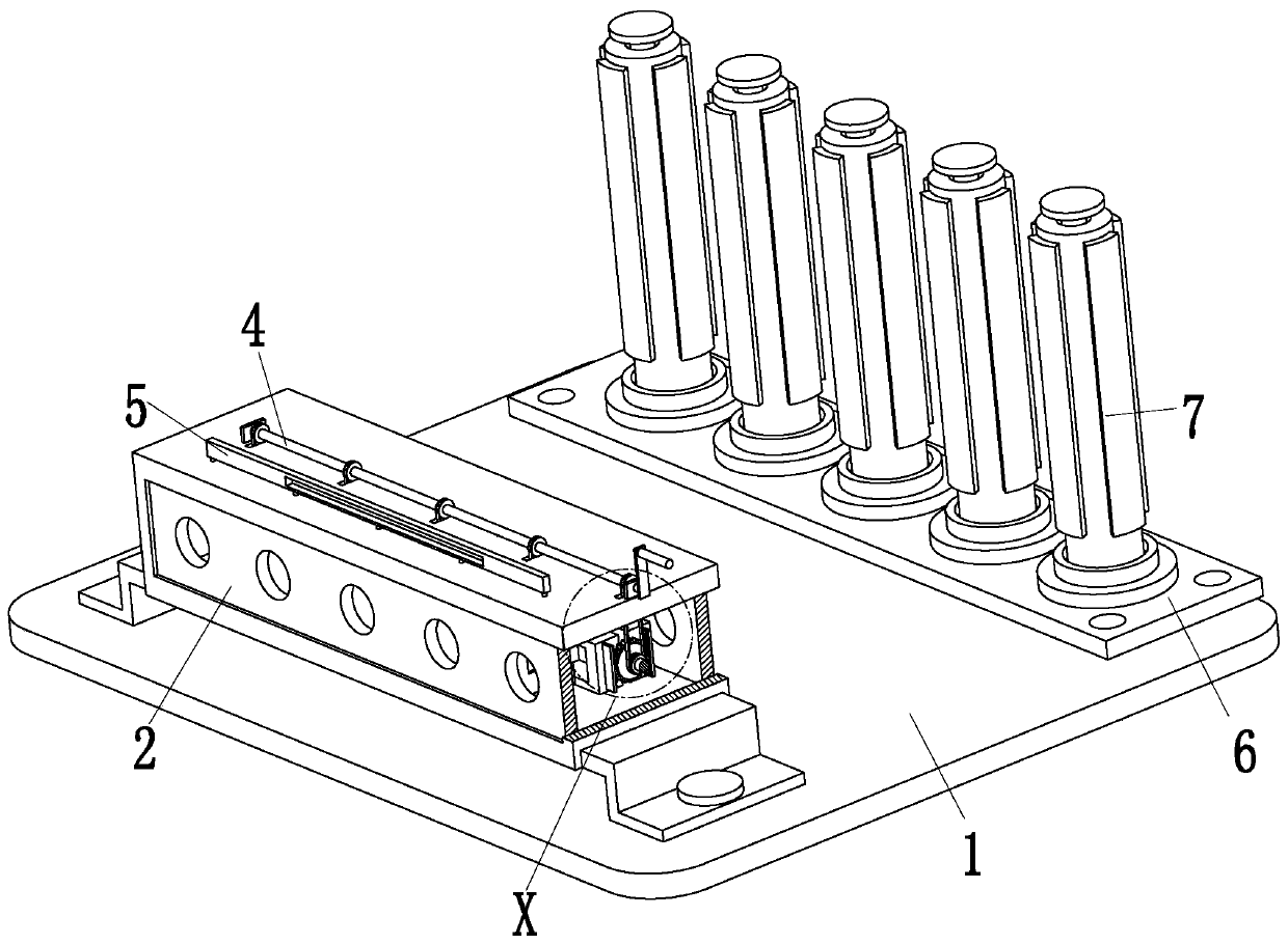
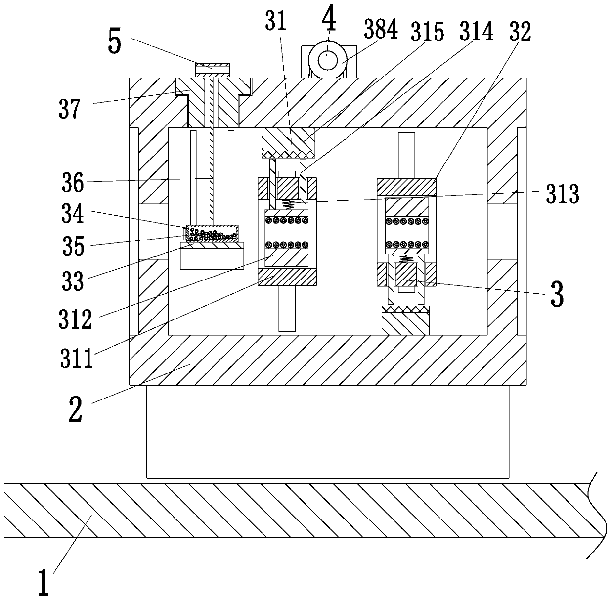
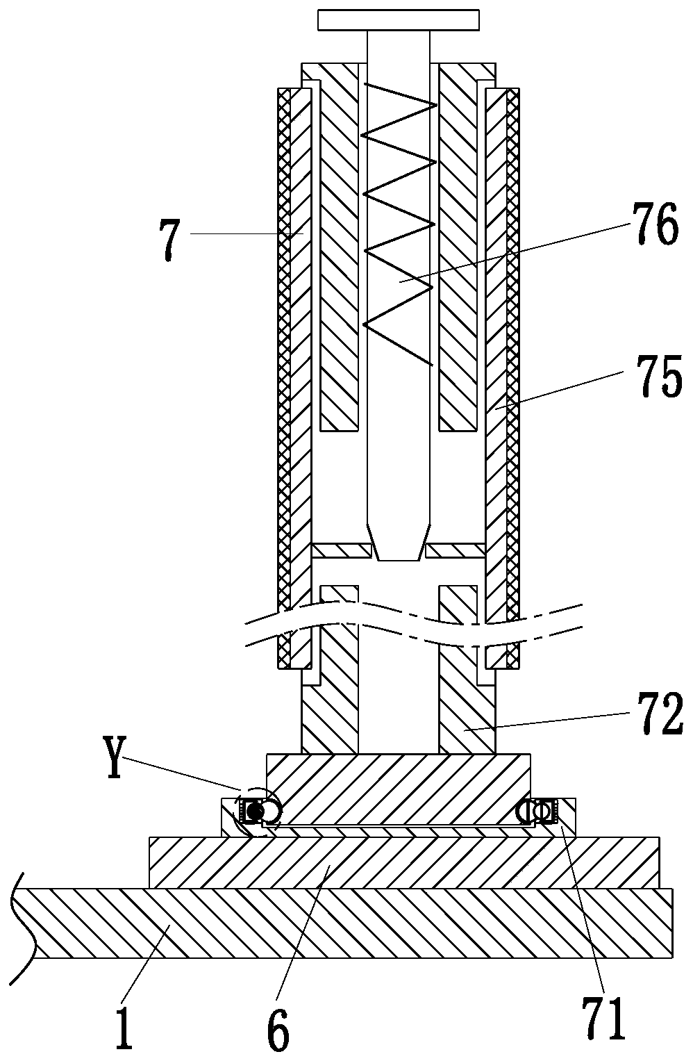
[0030] Such as Figure 1 to Figure 6 As shown, a yarn textile tensioning device includes a detachable base plate 1, a mounting frame 2, a tensioning unit 3, a positioning shaft 4, a linkage rod 5, a mounting plate 6 and a sleeve 7. The detachable base plate 1 The front end of the installation frame 2 is installed, and the interior of the installation frame 2 is evenly provided with a tension unit 3, the upper end of the tension unit 3 ...


PUM


Abstract

The invention relates to a yarn spinning tensioning device. The yarn spinning tensioning device comprises a detachable bottom plate, a mounting frame, tensioning units, a positioning rotating shaft, alinkage rod, a mounting plate and sleeves, wherein the mounting frame is mounted at the front end of the detachable bottom plate, the tensioning units are evenly arranged in the mounting frame, the upper ends of the tensioning units are connected with the positioning rotating shaft, the positioning rotating shaft is mounted at the upper end of the mounting frame through a bearing, the linkage rodis arranged in front of the positioning rotating shaft, the mounting plate is mounted at the rear end of the detachable bottom plate, and the sleeves are evenly arranged on the mounting plate. The problem that yarns can drive yarn bobbins to synchronously rotate at high speed after being drawn, when the drawing force suffered by the yarns disappears, the yarn bobbins still rotate for a while under the action of inertia, then the unwound yarns are not in a tensioned state at the moment, and the untightened yarns are prone to knotting after being subjected to secondary drawing force is solved.

Description

technical field [0001] The invention relates to the textile field, in particular to a yarn textile tensioning device. Background technique [0002] In the textile industry, the yarn is wound on the yarn bobbin, and the yarn bobbin is set on the yarn frame, and the yarn bobbin rotates on the yarn frame for the operation of the textile machine. The existing yarn bobbin It is directly sleeved on the column and rotates, and the yarn on the yarn drum is pulled to drive the yarn drum to rotate. However, some problems are often encountered during the yarn delivery process: [0003] 1. After the yarn is pulled, it will drive the yarn bobbin to rotate synchronously at a high speed. When the yarn is under the traction force and disappears, the yarn bobbin still rotates for a while under the action of inertia, so that the unwinding yarn is not in a tensioned state at this time. , the untightened yarn is prone to yarn knotting after being subjected to the traction force for the second ...

Claims


Application Information

Patent Timeline
Patent Type & Authority Applications(China)
IPC IPC(8): D03D47/34D04B15/44
CPCD03D47/34D04B15/44
Inventor 盛萍萍吴璇
Owner 安徽金弘润新材料科技有限公司
Why Eureka
Try Eureka