
Tow printing and dyeing device based on textile processing

A technology of tow and printing and dyeing box, applied in the field of textile processing, which can solve the problems of difficult separation of cotton tow, short time, color difference between edges, etc., and achieve the effects of uniform spreading speed and angle, uniform coloring, and wide range of pad dyeing

Inactive Publication Date: 2020-03-27
余亚萍
View PDF10 Cites 0 Cited by
  • Summary
  • Abstract
  • Description
  • Claims
  • Application Information

AI Technical Summary

Problems solved by technology

[0002] Tow refers to a basically untwisted long chemical fiber bundle formed by a large number of continuous filaments that are cut into short fibers or made into chemical fiber strips by stretching. A large number of single-strand filaments are assembled into tows. In the textile processing process, the existing technology for cotton tow printing and dyeing generally adopts the pad dyeing method. In continuous pad dyeing, the tows are bundled and immersed in the printing and dyeing solution. However, due to the extremely short time for continuous dyeing and padding, and the entanglement of bundled cotton tows, it is difficult to separate, which makes it impossible to balance the dyeing process, resulting in the problem of side-to-side color difference

Method used


Image

  • Tow printing and dyeing device based on textile processing
  • Tow printing and dyeing device based on textile processing
  • Tow printing and dyeing device based on textile processing

Examples


Embodiment

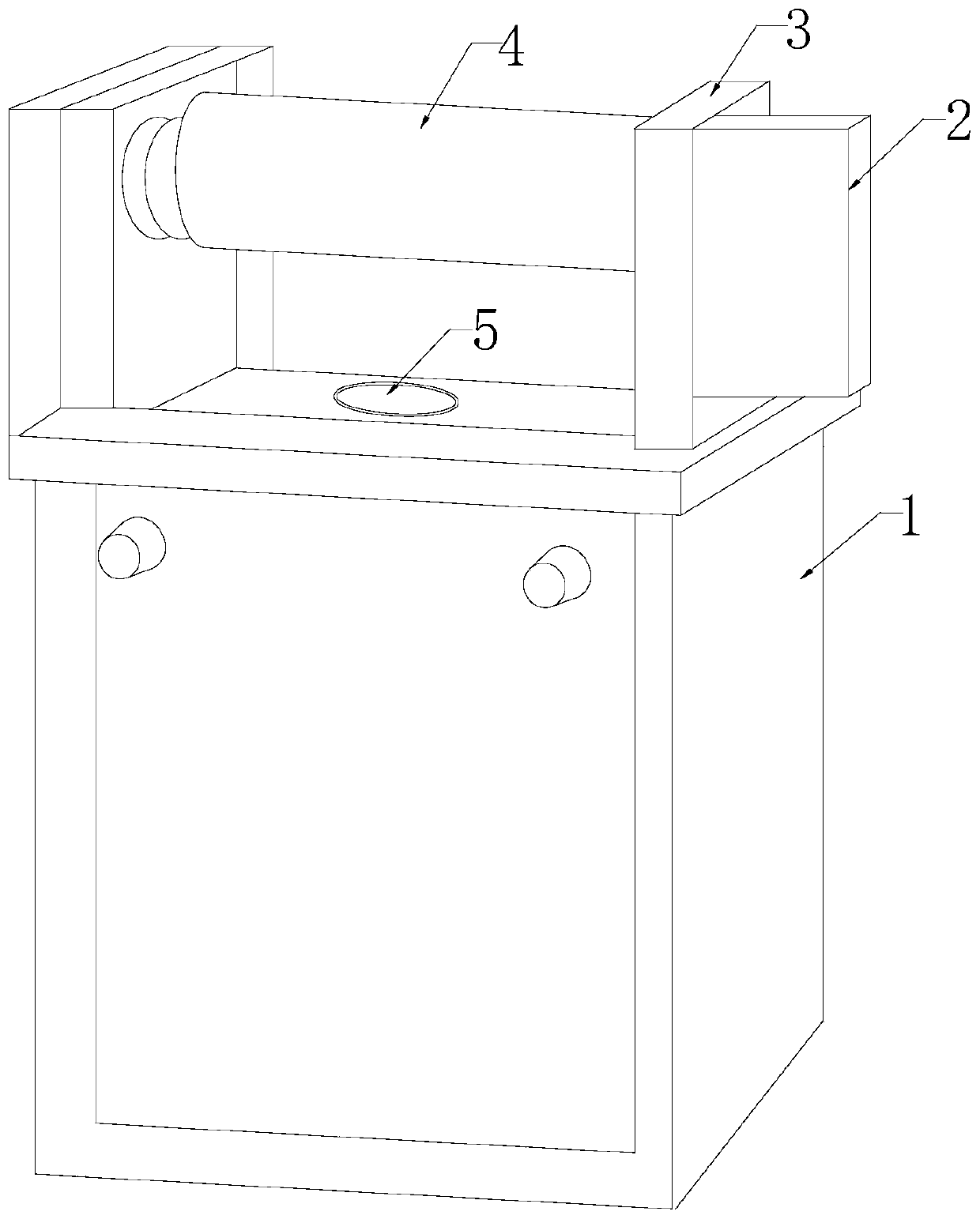
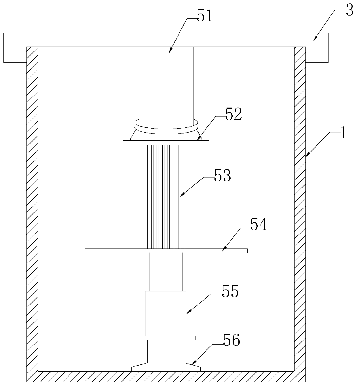
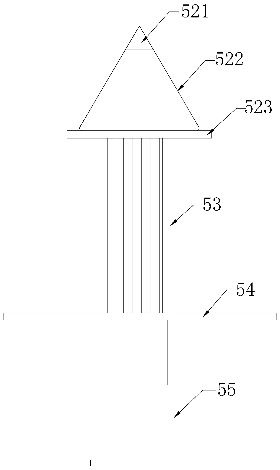
[0025] like Figure 1-Figure 5 As shown, the present invention provides a tow printing and dyeing device based on textile processing, and its structure includes a printing and dyeing box 1, an electric control box 2, a support 3, a drum 4, and a tow discharge port 5, and the printing and dyeing box 1 is welded with a bracket 3. A tow outlet 5 is provided between the support 3 and the printing and dyeing box 1, an electric control box 2 is installed on the support 3, and a movable part mechanically connected to the drum 4 is provided between the two opposite supports 3. The tow outlet 5 is located inside the printing and dyeing box 1 and is provided with a feeding cylinder 51, a splitting plate 52, an expansion unit 53, a slideway 54, a telescopic bottom shaft 55, and a supporting base 56. The splitting The top of the plate 52 passes through the inside of the feeding cylinder 51, and the bottom of the splitting plate 52 is fixed with an expansion part 53, and the expansion part...


PUM


Abstract

The invention discloses a tow printing and dyeing device based on textile processing. The tow printing and dyeing device based on textile processing structurally comprises a printing and dyeing box, an electric control box, brackets, a roller and a tow discharge port; the brackets are welded to the printing and dyeing box; the tow discharge port is formed between the brackets and the printing anddyeing box; the electric control box is mounted on the brackets; a movable port mechanically connected to the roller is arranged between the two opposite brackets; the tow discharge port is provided with a feeding cylinder, a filament splitting plate piece, an expansion and closing piece, a slideway, a telescopic bottom shaft and a supporting base inside the printing and dyeing box; the top end ofthe filament splitting plate piece penetrates into the feeding cylinder; the expansion and closing piece is fixed to the bottom of the filament splitting plate piece; the expansion and closing pieceis connected with the telescopic bottom shaft through the slideway in cooperation with the bottom end of the expansion and closing piece, the telescopic bottom shaft is mounted and fixed with the supporting base; the tow discharge port is vertically arranged in the printing and dyeing box, and tows are vertically fed, so that the tows can be uniformly distributed into each pad dyeing board slot incooperation with the filament splitting plate piece in the feeding cylinder, and the problem of poor chromatic aberration due to uneven dyeing caused by separation in bundles and difficulty in printing and dyeing is solved.

Description

technical field [0001] The invention relates to the field of textile processing, in particular to a tow printing and dyeing device based on textile processing. Background technique [0002] Tow refers to a basically untwisted long chemical fiber bundle formed by a large number of continuous filaments that are cut into short fibers or made into chemical fiber strips by stretching. A large number of single-strand filaments are assembled into tows. In the textile processing process, the existing technology for cotton tow printing and dyeing generally adopts the pad dyeing method. In continuous pad dyeing, the tows are bundled and immersed in the printing and dyeing solution. However, due to the extremely short time of continuous dyeing and padding, and the entanglement of bundled cotton tows, it is difficult to separate, so that the dyeing cannot be balanced, resulting in the problem of color difference in the edge. Contents of the invention [0003] In view of the above pro...

Claims


Application Information

Patent Timeline
IPC IPC(8): D06B3/04D06B23/04D06B23/18
CPCD06B3/045D06B23/04D06B23/18D06B2700/36
Inventor 余亚萍
Owner 余亚萍
Learn More