Bottom die trolley of short-line matching prefabricated box girder

A short-line matching and bottom mold technology, which is applied in the direction of erecting/assembling bridges, bridges, bridge materials, etc., can solve problems such as overturning, increased operating height, and high production costs, and achieve the effect of simple and efficient operation and reduced operating height

Pending Publication Date: 2020-03-27
湖南五新智能科技股份有限公司
View PDF0 Cites 3 Cited by
  • Summary
  • Abstract
  • Description
  • Claims
  • Application Information

AI Technical Summary

Problems solved by technology

[0004] First of all, it is bulky, and the three-story support structure leads to its own high height, which makes the center of gravity of the segmental beams it carries too high. During the adjustment of the matching beam, the center of gravity is too high, which may cause safety hazards of overturning, and all during the entire construction process The working height needs to be increased, and the equipment used in the construction process, including the height of the gantry crane, the height of the canopy, and the height of the beam lifting machine, etc. must be increased accordingly; secondly, the three-layer structure of the bottom mold trolley needs to be adjusted with each other, the structure is complex, and the adjustment time long; then due to its large volume and complex structure, its production cost is relatively high

Method used


Image

  • Bottom die trolley of short-line matching prefabricated box girder
  • Bottom die trolley of short-line matching prefabricated box girder
  • Bottom die trolley of short-line matching prefabricated box girder

Examples


Embodiment Construction

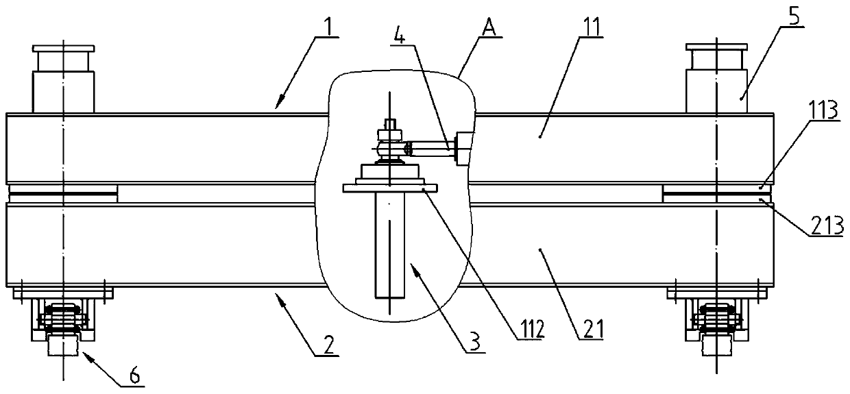
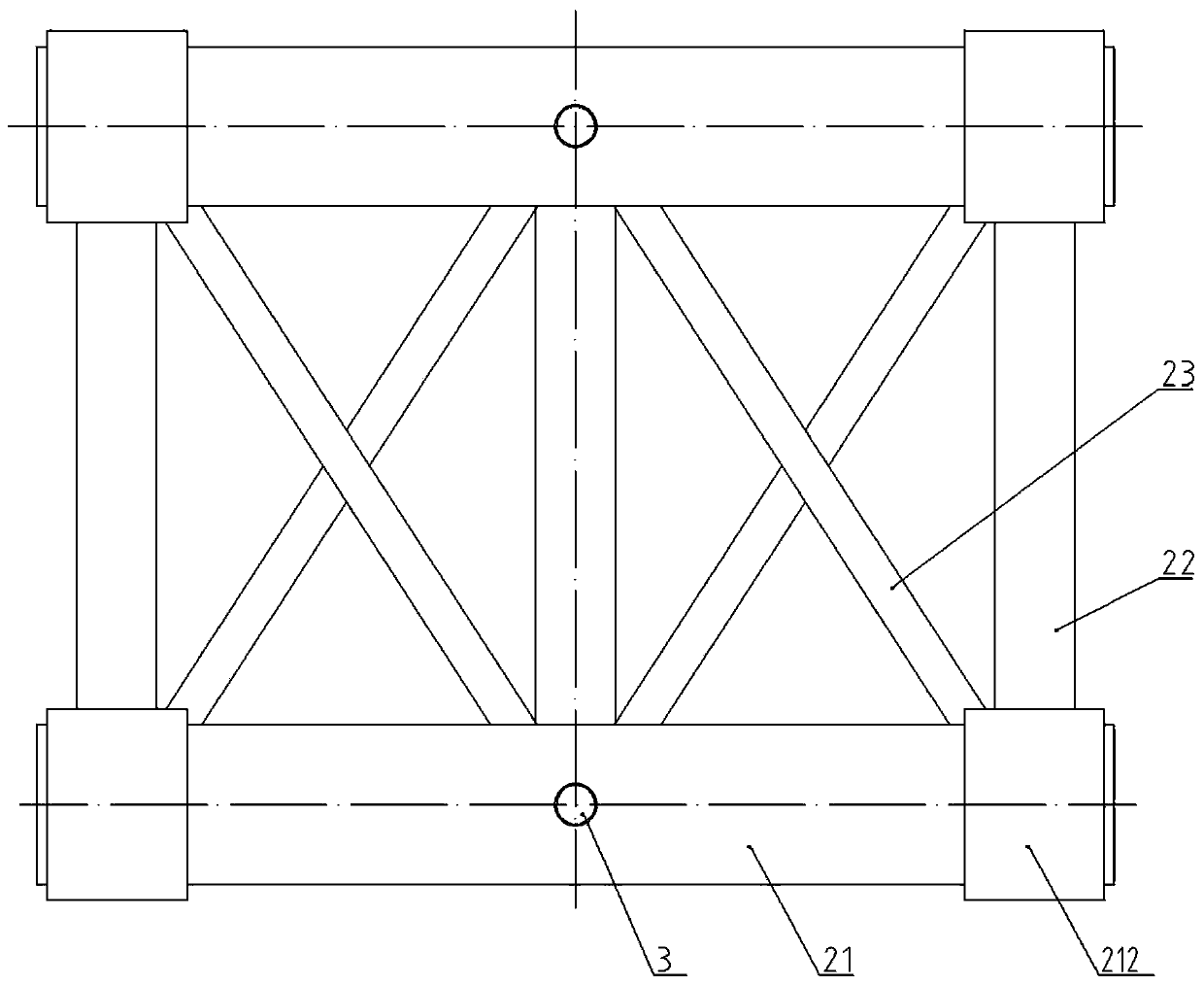
[0024] like figure 1 As shown, the bottom mold trolley for short-line matching prefabricated box beams disclosed in this embodiment includes an upper bracket 1 , a lower bracket 2 , a limit post 3 , an adjustment device 4 , a jacking device 5 , and a running device 6 .

[0025] The upper bracket 1 and the lower bracket 2 are square frames with the same plane size.

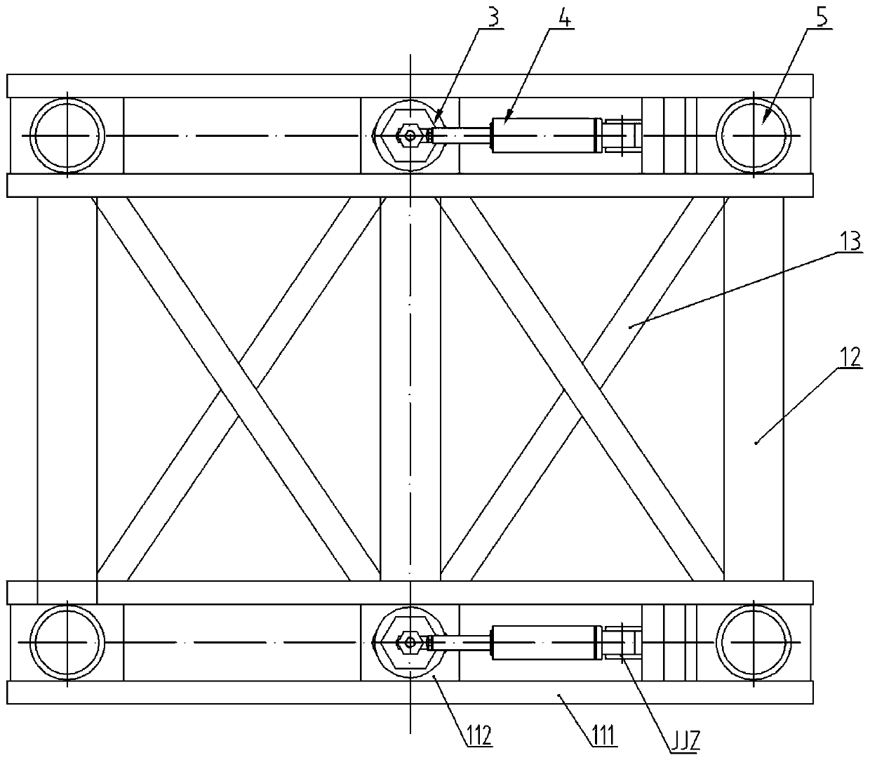
[0026] combine figure 1 , figure 2 and Figure 5 It can be seen that the upper bracket 1 is welded into a square frame by the upper beam 11 , the upper longitudinal beam 12 and the upper reinforcing beam 13 .

[0027] The upper beam 11 includes a channel steel 111, a middle connecting plate 112 and an end connecting plate 113. The two channel steels 111 are symmetrically arranged with openings facing each other with a gap, so that a transverse groove is formed between the two channel steels, and the middle connecting plate 112 is welded on. On the bottom surface of the middle position in the length direction o...


PUM


Abstract

The invention discloses a bottom die trolley of a short-line matching prefabricated box girder. The bottom die trolley comprises an upper-layer support, a lower-layer support, an adjusting device, a jacking device and a walking device. The two supports are vertically stacked, and are small in size and low in center of gravity. The walking devices are connected to the bottoms of the two transversesides of the lower-layer support. Vertical limiting columns are connected to the middle positions of the front end and the rear end of the lower-layer bracket; the limiting column penetrates through the upper-layer support to enable the two supports to be vertically limited through a fastener, the adjusting device is a telescopic device arranged in the horizontal direction, one end of the adjusting device is hinged to a hinge base on the upper-layer support, the other end of the adjusting device is hinged to the limiting column and vertically limited, and the multiple jacking devices are vertically connected to the upper-layer support. Horizontal transverse movement of the upper-layer support relative to the lower-layer support and rotation of the upper-layer support around the limiting column on one side can be achieved through telescopic movement of the adjusting device, the jacking device is used for jacking the matching beam, the vertical height or inclination angle of the matchingbeam can be adjusted, longitudinal movement of the matching beam carried by the bottom die trolley is achieved through the walking device, and operation is easy.

Description

technical field [0001] The invention belongs to the field of short-line matching prefabricated box girders, in particular to a bottom mold trolley for short-line matching prefabricated box girders. Background technique [0002] In the construction of short-line matching prefabricated segmented box girder, the function of the bottom mold trolley is to smoothly move the prefabricated segment beam and its lower bottom mold from the prefabrication station to the matching station, and adjust the three-dimensional space of the segment at the same time. position to match the segment to be prefabricated to ensure the overall line shape of the box girder. [0003] At present, the commonly used bottom mold trolley is composed of three layers of supports, which can adjust the three-dimensional spatial position of the matching beam, but there are many problems with the bottom mold cart: [0004] First of all, it is bulky, and the three-layer support structure leads to its own high heig...

Claims


Application Information

Patent Timeline
Patent Type & Authority Applications(China)
IPC IPC(8): E01D21/06E01D101/24E01D2/04
CPCE01D2/04E01D21/06E01D2101/24
Inventor 蒋平文杨波李辉辜天天黄浪徐彪彪
Owner 湖南五新智能科技股份有限公司
Why Eureka
Try Eureka