Assembly member and mounting method

A technology of components and locking parts, which is applied in the direction of building components, building structures, floors, etc., can solve the problems of difficult installation and recycling of existing walls, problems in the maintenance of prefabricated walls, and complex construction techniques, etc., to achieve Convenient assembly and later disassembly and reassembly, shortening the construction period, and strong installation flexibility

Inactive Publication Date: 2020-03-27
JIANGSU DONGZHAO CONSTR IND INNOVATION & DEV RES INST CO LTD
View PDF7 Cites 0 Cited by
  • Summary
  • Abstract
  • Description
  • Claims
  • Application Information

AI Technical Summary

Problems solved by technology

[0003] At present, the interior space division of many buildings is composed of fixed walls or prefabricated walls. In recent years, prefabricated walls are more constructed by manufacturing and assembling multiple panels rather than by a large number of processes; however, the existing Prefabricated walls focus on the assembly of materials rather than disassembly, so it is difficult to move and recycle the built walls
[0004] Existing prefabricated walls are composed of pillars, formwork, fixed components, finishing components and many other components, making construction difficult
In addition, it is impossible to modify according to the conditions of the construction site, and even the electric wires or cooling equipment need to be manufactured conventionally, the construction process is complex and time-consuming, and there are problems in the maintenance of prefabricated walls

Method used


Image

  • Assembly member and mounting method
  • Assembly member and mounting method
  • Assembly member and mounting method

Examples


Embodiment 1

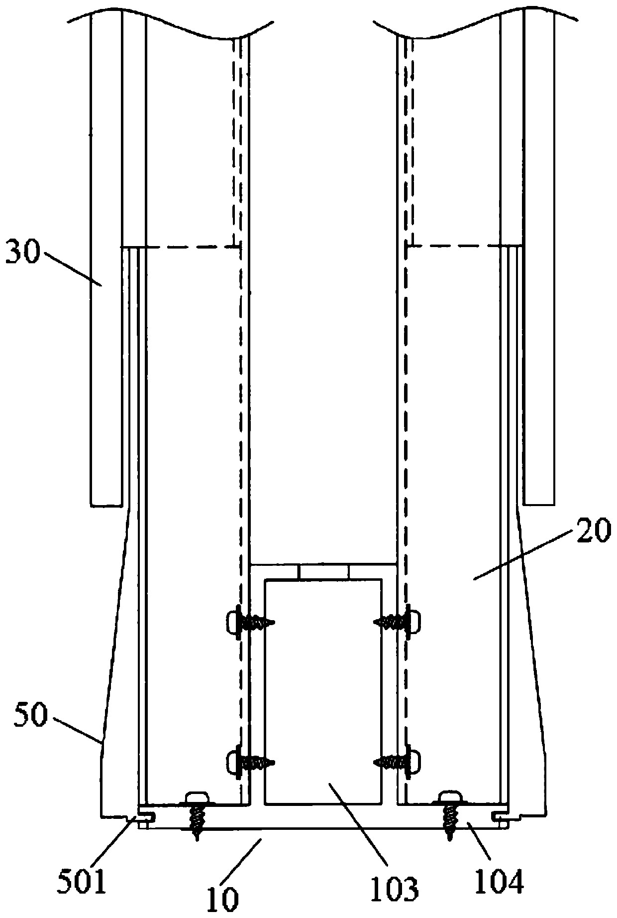
[0040] as attached figure 1 As shown, a component for assembly includes a frame and a panel 30, and the panel 30 is fixed on the frame.

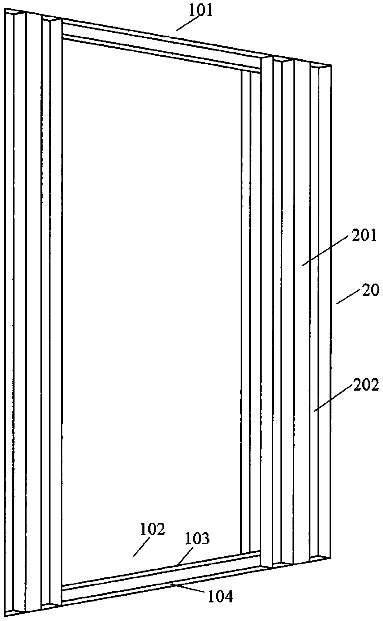
[0041] as attached figure 2 As shown, the frame includes a fixed plate 10 and a fixed column 20, the fixed plate 10 includes a first fixed plate 101 and a second fixed plate 102, and the two ends of the fixed column 20 are respectively fixed on the first fixed plate 101 and the second fixing plate 102 ; the panel 30 is fixed on the fixing column 20 .

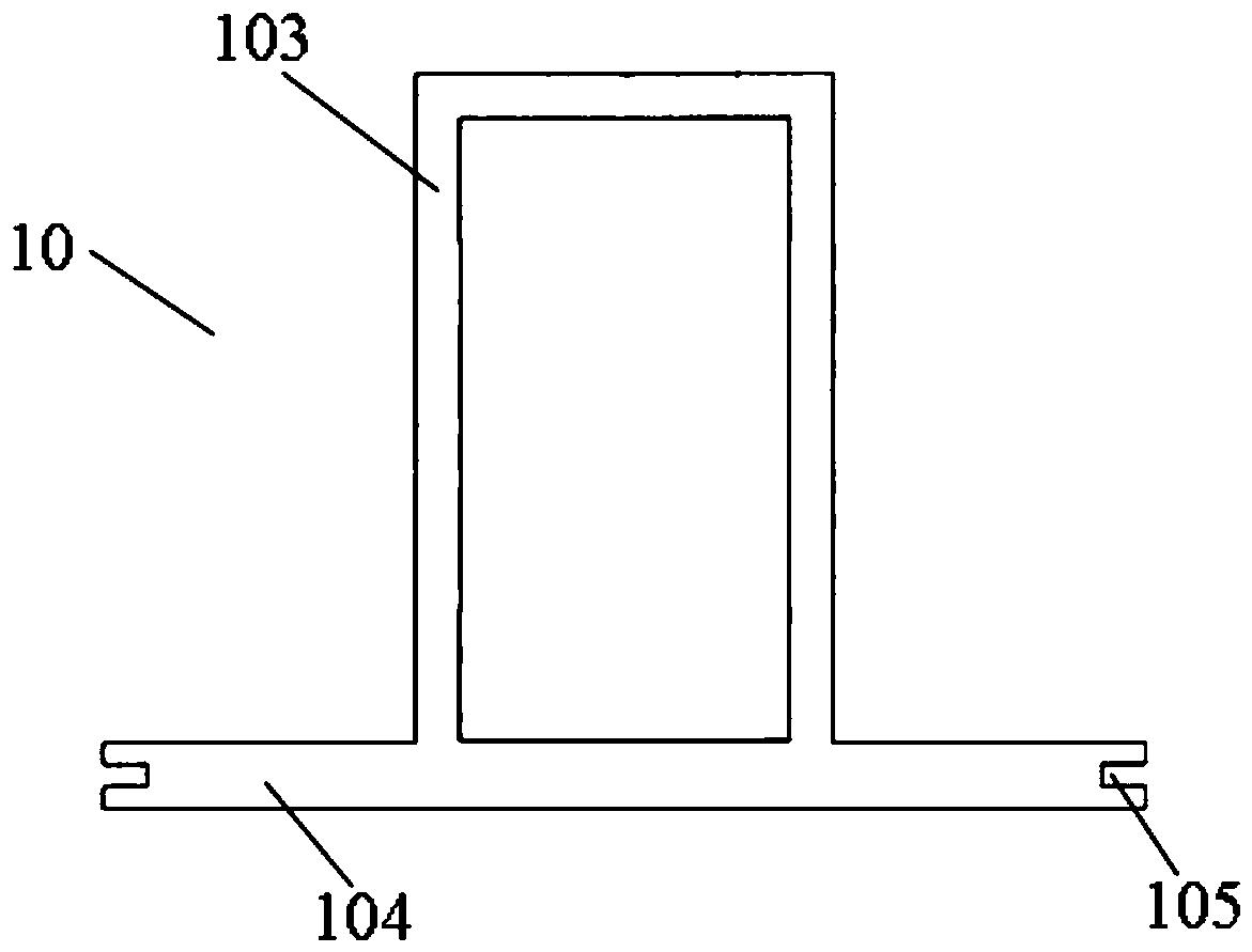
[0042] as attached image 3 As shown, the fixed plate 10 is a "convex" structure, and a first boss 103 is arranged in the middle. The first boss 103 is a hollow structure, and side plates 104 are arranged on both sides of the first boss 103. The side board 104 is used to be fixed on the ceiling or the floor.

[0043] Preferably, a through hole is provided above the first boss 103, and the through hole is used for wires to pass through.

[0044] as attached Figure 4 As shown, the fixing...

Embodiment 2

[0051] Based on the above-mentioned embodiment 1, a method for installing components for assembling comprises the following steps:

[0052] 101. First fix the first fixing plate 101 and the second fixing plate 102 on the ceiling and the floor respectively by screws, that is, the side plates 104 of the first fixing plate 101 and the second fixing plate 102 are fixed on the ceiling and the floor by screws;

[0053] 102. After step 101, fix the two ends of the fixed column 20 on the first fixed plate 101 and the second fixed plate 102 respectively, that is, the grooves 202 at both ends of the fixed column 20 are fixed on the first fixed plate 101 and the second fixed plate 102 by screws. On the first boss 103 of the fixed plate 102;

[0054] 103. After step 102, fix one side of the panel 30 on the fixed column 20 through the coupling 40, firstly connect the panel 30 to the coupling 40 with screws, and then fix the coupling 40 on the fixed column 20 Inside the groove 202;

[005...

Embodiment 3

[0058] Based on the above-mentioned embodiment 1, a method for installing components for assembling comprises the following steps:

[0059] 101. First, fix the first fixing plate 101 and the second fixing plate 102 to the ceiling and the floor respectively by screws, that is, the side panels 104 of the first fixing plate 101 and the second fixing plate 102 are fixed to the ceiling and the floor by screws superior;

[0060] 102. After step 101, fix the two ends of the two fixed columns 20 on the first fixed plate 101 and the second fixed plate 102 respectively, that is, the grooves 202 at both ends of the fixed column 20 are fixed on the first fixed plate 101 and the second fixed plate 102 by screws. On the first boss 103 of the second fixing plate 102, two fixing columns 20 are fixed on both sides of the fixing plate 10 front and back;

[0061] 103. After step 102, fix one side of the two panels 30 on the two front and rear fixing columns 20 respectively through the coupling ...


PUM


Abstract

The invention relates to an assembly member and a mounting method. The member comprises a frame and a panel. The frame comprises a fixed plate and a fixed column; the fixed plate comprises a first fixed plate body and a second fixed plate body, and the two ends of the fixed column are fixed to the first fixed plate body and the second fixed plate body respectively. The panel is fixed on the fixedcolumn. The mounting method is simple to operate, convenient to use and high in mounting efficiency. According to the invention, the used screws are reduced to the maximum extent, the installation, disassembly and reassembly of the wall body are facilitated, a small amount of personnel are allowed to simultaneously carry out installation or disassembly work, the labor cost is reduced, the construction period can be shortened, the installation flexibility is strong, and the member and method are suitable for assembling wall body structures with different structures.

Description

technical field [0001] The invention relates to the technical field of building construction, in particular to a component for assembly and an installation method. Background technique [0002] The prefabricated building is mainly based on concrete prefabricated components, and is a building structure formed through on-site assembly, connection and cast-in-place congratulations. Compared with traditional building construction methods, prefabricated buildings can save construction time, fast construction speed, basically not affected by climate conditions during construction, reduce on-site construction personnel, reduce pollution during construction, and achieve social benefits. [0003] At present, the interior space division of many buildings is composed of fixed walls or prefabricated walls. In recent years, prefabricated walls are more constructed by manufacturing and assembling multiple panels rather than by a large number of processes; however, the existing Prefabrica...

Claims


Application Information

Patent Timeline
Patent Type & Authority Applications(China)
IPC IPC(8): E04B2/74E04B2/82E04B1/82
CPCE04B1/82E04B2/74E04B2/82
Inventor 殷惠君孙峰曹爱壮
Owner JIANGSU DONGZHAO CONSTR IND INNOVATION & DEV RES INST CO LTD
Why Eureka
Try Eureka