Drum brake and vehicle brake system

A drum brake and brake shoe technology, applied in the field of vehicles, can solve problems such as high maintenance costs, vehicle brake deviation, and impact on driving safety, so as to reduce maintenance costs, prevent dragging, and ensure driving safety. Effect

Active Publication Date: 2020-03-27
湖南中联重科车桥有限公司
View PDF12 Cites 0 Cited by
  • Summary
  • Abstract
  • Description
  • Claims
  • Application Information

AI Technical Summary

Problems solved by technology

In addition, during the use of the brake, wear and tear will inevitably occur, so the follow-up maintenance needs to regularly replace the brake shoe bushing 19, the bottom plate bushing 25 and the bracket bushing 26, resulting in high maintenance costs
[0006] Further, the clearance fit is affected by gravity, which will cause inconsistent clearance between the friction plate 27 and the brake drum 23, specifically, as figure 2 As shown, the gap between the friction plate 27 and the brake drum 23 on the upper brake shoe assembly 2 is larger than the gap between the friction plate 27 and the brake drum 23 of the lower brake shoe assembly 3, which will cause the braking torque of the left and right brakes of the vehicle Inconsistency, causing vehicle braking deviation
During the braking process, friction between the friction plate 27 with a small gap and the brake drum 23 will cause friction, which will cause the high temperature of the brake and cause the tire to catch fire, affecting driving safety.
[0007] In addition, if the gap between the friction plate 27 and the brake drum 23 is too small (less than the design requirement), it will also affect the automatic adjustment of the adjustment arm assembly, which will easily lead to over-adjustment of the adjustment arm assembly, and then make the vehicle brake When running, the brake temperature is too high
And because the inner hole of the brake shoe bushing 19 and the outer diameter of the brake shoe pin shaft 4 adopt clearance fit, under the action of the return spring 20, the cylindrical surface where the brake shoe assembly friction plate 27 is located forms a taper, which also causes friction. The gap between the disc 27 and the brake drum 23 is inconsistent, resulting in insufficient contact between the brake drum 23 and the friction disc 27, resulting in unstable braking torque and large fluctuations, which ultimately affects the braking effect

Method used


Image

  • Drum brake and vehicle brake system
  • Drum brake and vehicle brake system
  • Drum brake and vehicle brake system

Examples


Embodiment Construction

[0037] Specific embodiments of the present invention will be described in detail below in conjunction with the accompanying drawings. It should be understood that the specific embodiments described here are only used to illustrate and explain the present invention, and are not intended to limit the present invention.

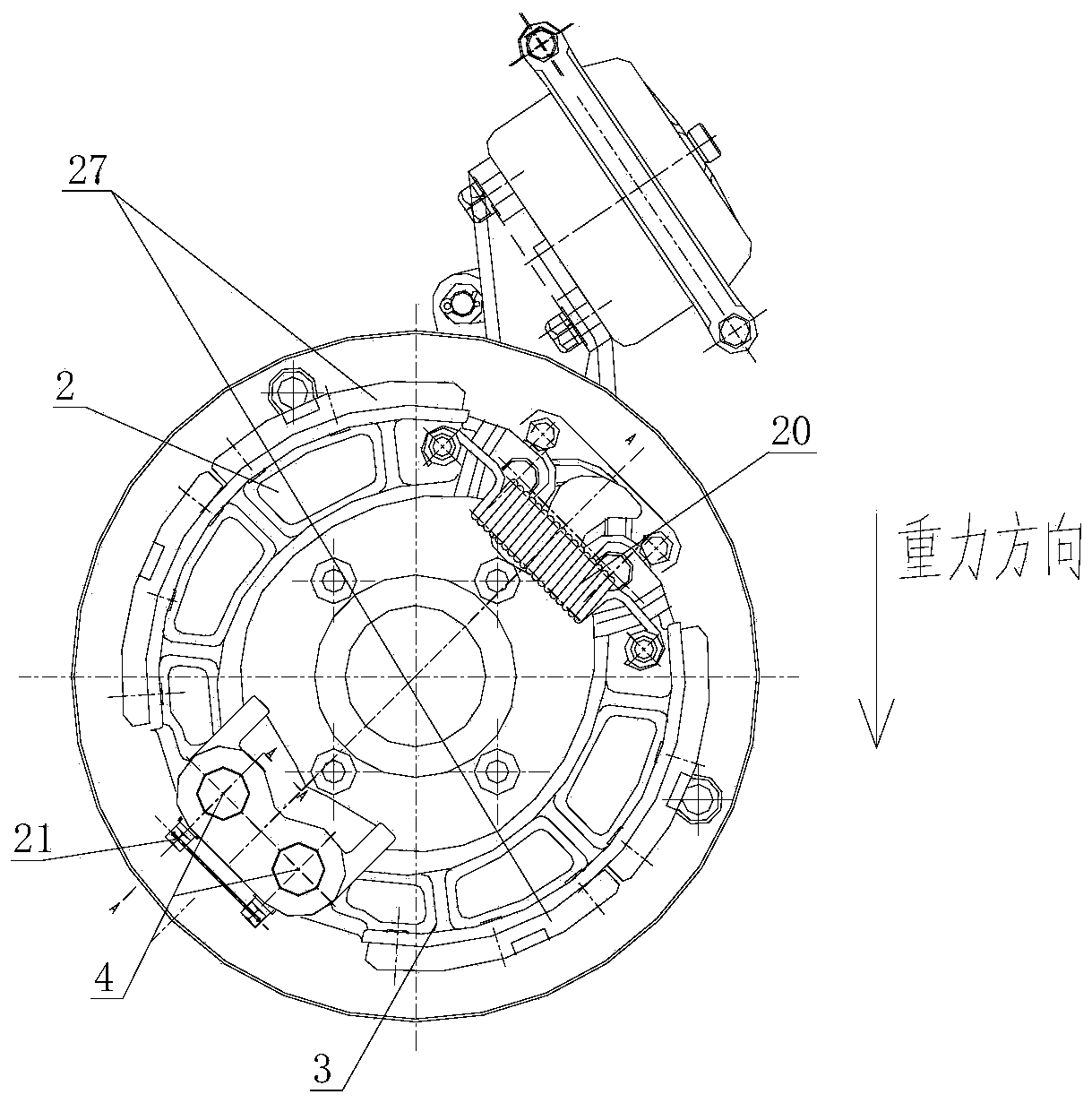
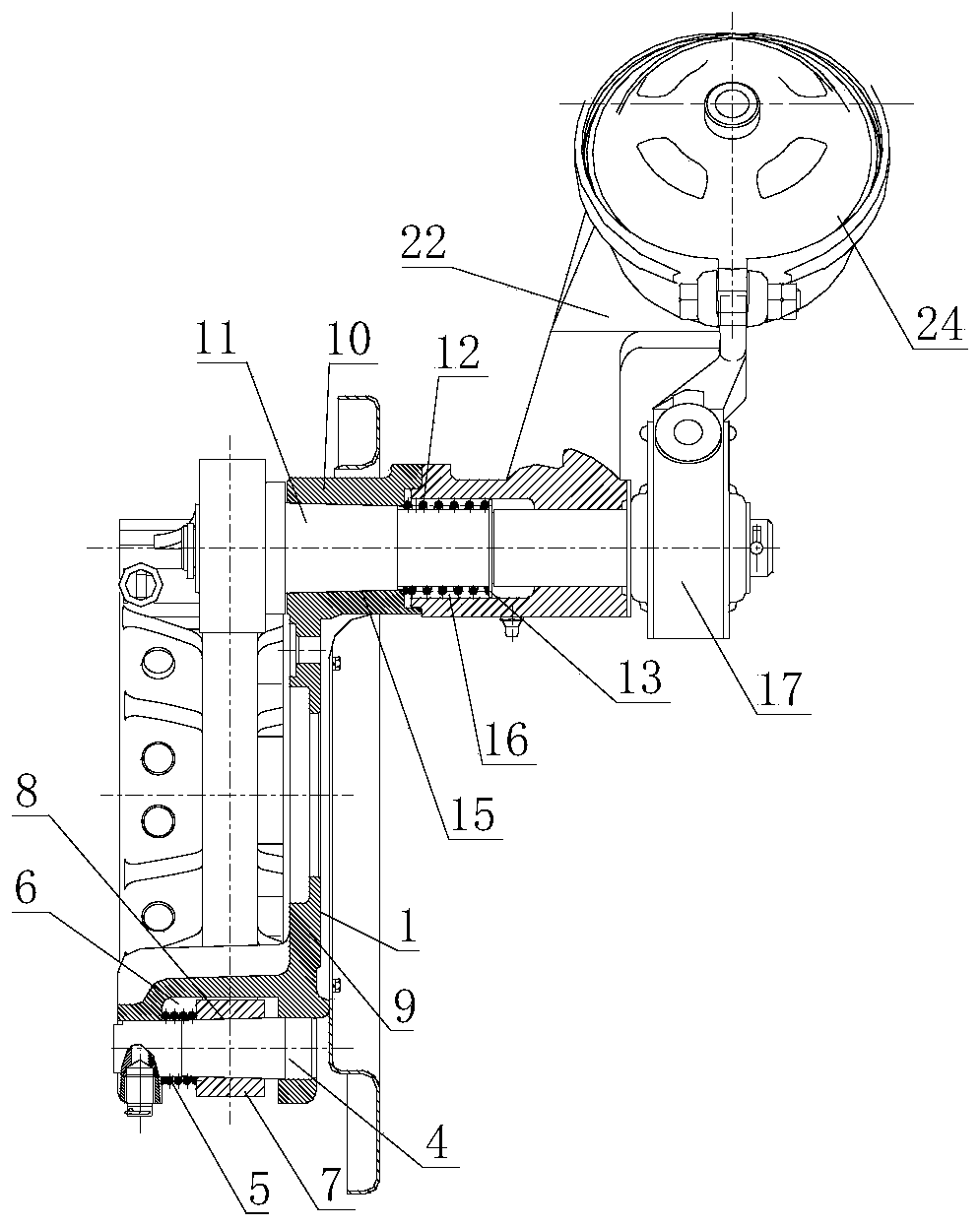
[0038] combine Figure 3-Figure 8 According to one aspect of the present invention, a drum brake is provided, comprising:

[0039] Brake base 1;

[0040] A brake shoe assembly, the brake shoe assembly is mounted on the brake base plate 1 through a brake shoe pin 4, and the brake shoe pin 4 is set to gradually increase in diameter along the axial direction; and

[0041] The first elastic member 5 is configured to provide a biasing force to the brake shoe assembly in a direction in which the diameter of the brake shoe pin 4 increases.

[0042]Through the above-mentioned technical solution, the drum brake of the present invention sets the brake shoe pin shaft to...


PUM


Abstract

The invention relates to the field of vehicles, and discloses a drum brake and a vehicle braking system. The drum brake comprises a brake bottom plate (1); a brake shoe assembly which is installed onthe brake bottom plate (1) through a brake shoe pin shaft (4), wherein the diameter of the brake shoe pin shaft (4) is gradually increased in the axial direction; and a first elastic part (5) which isarranged to be capable of providing a bias force towards the diameter increasing direction of the brake shoe pin shaft (4) for the brake shoe assembly (1). According to the drum brake, the brake shoeassembly is pushed to move under the action of the first elastic part so as to automatically compensate the gap between the brake shoe pin shaft and the brake shoe assembly caused by abrasion betweenthe brake shoe pin shaft and the brake shoe assembly, and the zero-gap fit between the brake shoe pin shaft and the brake shoe assembly is achieved.

Description

technical field [0001] The invention relates to the technical field of vehicles, in particular to a drum brake and a vehicle braking system. Background technique [0002] The brake is an important component on the automobile axle, which has a vital impact on driving safety. The consistency of the friction plate of the brake shoe assembly and the gap between the brake drum has the greatest impact on the braking of the whole vehicle. [0003] At present, pneumatic drum brakes such as figure 1 As shown, the upper brake shoe assembly 2 and the lower brake shoe assembly 3 are installed on the brake base plate 1 through the brake shoe pin shaft 4 and the set screw 18, and the upper brake shoe assembly 2 and the lower brake shoe assembly The inner hole of the assembly 3 and the brake shoe bushing 19 adopt an interference fit, and the inner hole of the brake shoe bushing 19 and the outer diameter of the brake shoe pin 4 adopt a clearance fit; the return spring 20 is connected to th...

Claims


Application Information

Patent Timeline
Patent Type & Authority Applications(China)
IPC IPC(8): F16D51/24F16D51/22F16D65/08F16D65/09F16D121/14F16D125/30
CPCF16D51/22F16D51/24F16D65/08F16D65/09F16D2121/14F16D2125/30
Inventor 李晓辉刘四清文峻杨峰
Owner 湖南中联重科车桥有限公司
Why Eureka
Try Eureka