Mirror surface display panel, manufacturing method thereof and mirror surface display device

A technology for a display panel and a manufacturing method, which is applied in the manufacture of semiconductor/solid-state devices, semiconductor devices, electrical components, etc., can solve the problems of lowering display brightness, lowering the transmittance of pixel display area, etc., so as to improve display brightness and improve light transmission. The effect of avoiding the influence of light transmittance and light transmittance

Active Publication Date: 2020-03-27
BOE TECH GRP CO LTD +1
View PDF2 Cites 9 Cited by
  • Summary
  • Abstract
  • Description
  • Claims
  • Application Information

AI Technical Summary

Problems solved by technology

[0003] Among them, the traditional mirror display mostly uses a semi-transparent and semi-reflective film attached to the LCD (liquid crystal) display device to completely cover the pixel display area and the non-pixel display area to achieve a mirror display. Although the display device produced by this method can realize mirror Display, but greatly reduces the transmittance of the pixel display area, and reduces the display brightness

Method used


Image

  • Mirror surface display panel, manufacturing method thereof and mirror surface display device
  • Mirror surface display panel, manufacturing method thereof and mirror surface display device
  • Mirror surface display panel, manufacturing method thereof and mirror surface display device

Examples


Embodiment Construction

[0055] Example embodiments will now be described more fully with reference to the accompanying drawings. Example embodiments may, however, be embodied in many forms and should not be construed as limited to the examples set forth herein; rather, these embodiments are provided so that this application will be thorough and complete, and will fully convey the concepts of example embodiments to those skilled in the art. The described features, structures, or characteristics may be combined in any suitable manner in one or more embodiments. In the following description, numerous specific details are provided in order to give a thorough understanding of the embodiments of the application.

[0056] In the drawings, the thicknesses of regions and layers may be exaggerated for clarity. The same reference numerals in the drawings denote the same or similar structures, and thus their detailed descriptions will be omitted.

[0057]The described features, structures, or characteristics ...


PUM


Abstract

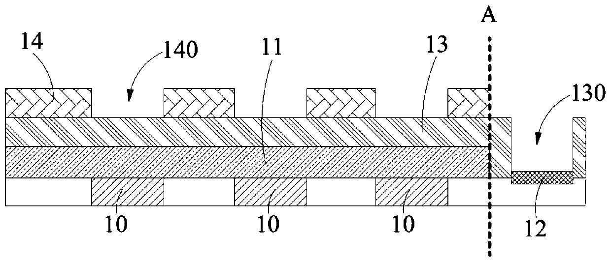
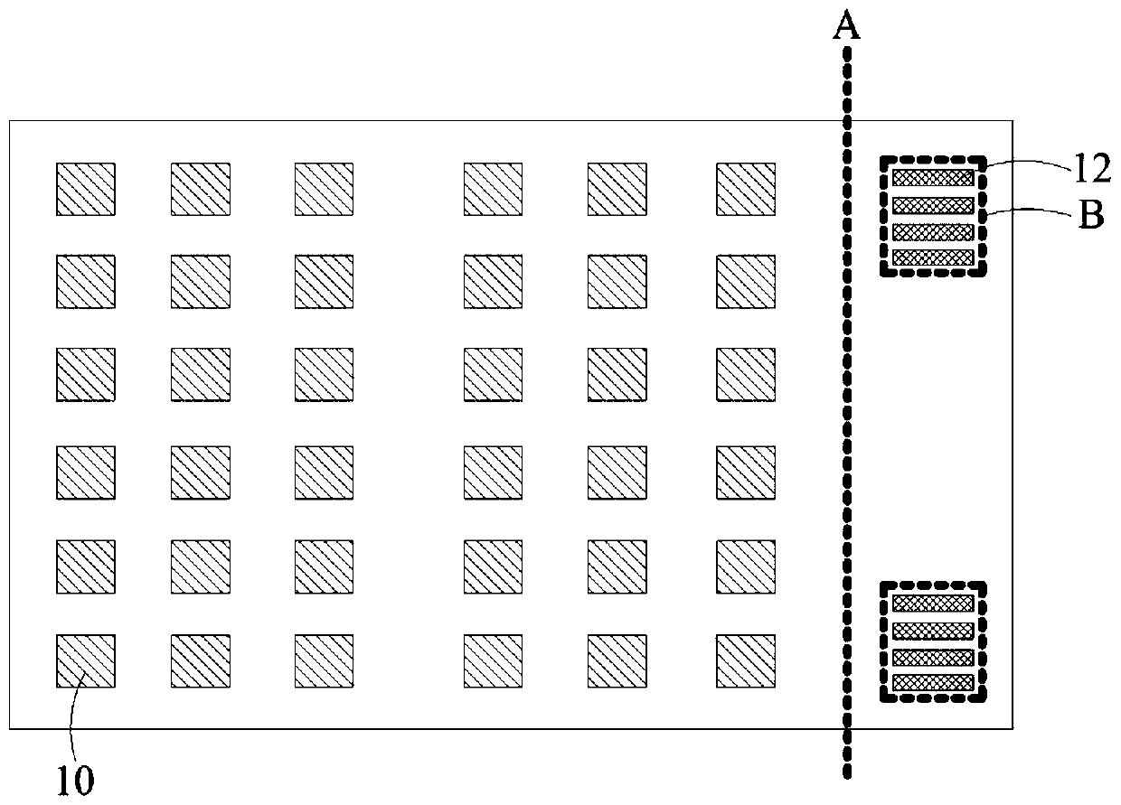
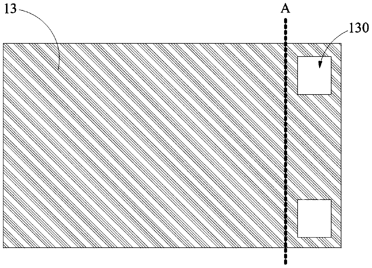
The invention provides a mirror surface display panel, a preparation method thereof and a mirror surface display device, and belongs to the technical field of display. The mirror surface display panelcomprises: a display substrate having a display area and a non-display area located at the periphery of the display area, wherein the display area comprises a plurality of organic light-emitting diodes arranged in an array and a packaging film covering the organic light-emitting diodes, the non-display area comprises a binding position, and the binding position is provided with a plurality of binding pins arranged at intervals; an inorganic protective layer is formed on the display substrate and covers the display area and the non-display area, and the inorganic protective layer is provided with a first hollow hole corresponding to the binding position; and a metal reflection layer is formed on one side, deviating from the packaging film, of the inorganic protection layer, and the metal reflection layer is provided with a second hollow hole corresponding to the organic light emitting diode. According to the mirror surface display panel, while mirror surface display is achieved, the light transmittance can be improved, and the manufacturing yield of the mirror surface display panel is guaranteed.

Description

technical field [0001] The present application relates to the field of display technology, in particular to a mirror display panel, a manufacturing method thereof, and a mirror display device. Background technique [0002] At present, the market demand for products that combine mirrors and displays is becoming more and more widespread. They are not only applied to home furnishing, shopping malls, advertising, beauty and cosmetics, but also to vehicle rearview mirrors and other application scenarios. [0003] Among them, the traditional mirror display mostly uses a semi-transparent and semi-reflective film attached to the LCD (liquid crystal) display device to completely cover the pixel display area and the non-pixel display area to achieve a mirror display. Although the display device produced by this method can realize mirror Display, but the transmittance of the pixel display area is greatly reduced, and the display brightness is reduced. [0004] The above information di...

Claims


Application Information

Patent Timeline
Patent Type & Authority Applications(China)
IPC IPC(8): H01L27/32H01L51/52H01L51/56
CPCH10K59/12H10K50/844H10K59/1201H10K71/00
Inventor 张兵梁翠翠
Owner BOE TECH GRP CO LTD
Why Eureka
Try Eureka