A mobile cable holder

A cable support and mobile technology, applied in electrical components and other directions, can solve problems such as low fault tolerance, hindering the smooth installation of supports, bridges, and load-bearing damage to the upper floor, achieving good reliability, avoiding damage, and improving stability.

Active Publication Date: 2022-01-21
RES INST OF ECONOMICS & TECH STATE GRID SHANDONG ELECTRIC POWER +3
View PDF8 Cites 0 Cited by
  • Summary
  • Abstract
  • Description
  • Claims
  • Application Information

AI Technical Summary

Problems solved by technology

The fixing method of embedded parts requires accurate estimation of the installation foot position of each bracket during engineering design, and pre-buried in the ground or roof structure layer before the installation of brackets and bridges. If there is position deviation or error during bracket installation , the embedded part will lose its intended purpose, directly hindering the smooth installation of brackets and bridges, and the fault tolerance rate is extremely low; the expansion bolt fixing method needs to drill holes on the installation surface during installation, and the drilling holes are very dense, especially for cables. Drilling holes on the first floor roof structure will directly cause damage to the load-bearing of the upper floor slab

Method used


Image

  • A mobile cable holder
  • A mobile cable holder
  • A mobile cable holder

Examples


Embodiment 1

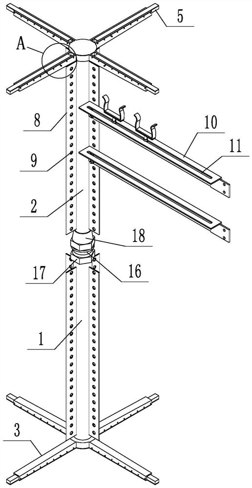
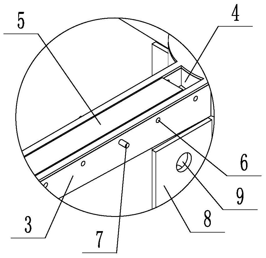
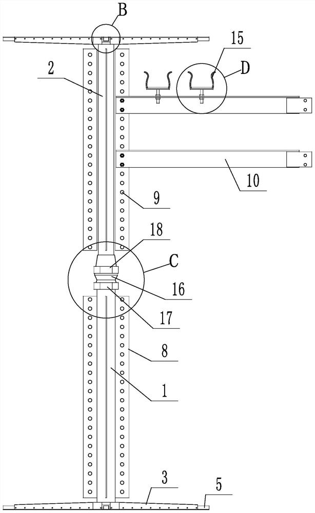
[0035] Such as Figure 1 to Figure 7As shown, a mobile cable support includes a lower support rod 1, an upper support rod 2 and a cross brace 10, the lower end of the upper support rod 2 penetrates into the lower support rod 1 and is slidably connected with the lower support rod 1, and the lower support rod A drive mechanism for driving the upper support rod 2 to move up and down is provided between the rod 1 and the upper support rod 2, the lower end of the lower support rod 1 and the upper end of the upper support rod 2 are provided with a support 3, and the support 3 of the lower support rod 1 Supported on the ground, the upper support rod 2 is driven upward by the driving mechanism, so that the support 3 of the upper support rod 2 is supported on the ceiling, so as to realize the fixation of the bracket, without setting any embedded parts and expansion bolts for fixing, and the installation position can be adjusted Freely set according to the cable path, simple engineering...

Embodiment 2

[0043] Such as Figure 8 As shown, the upper support rod 2 is provided with a first drive rod 24, and the upper support rod 2 is provided with an internal thread. The lower end of the first drive rod 24 is connected to the inner wall of the lower support rod 1 through bearing rotation. The rod 24 is threadedly connected with the inner wall of the upper support rod 2, the side wall of the lower support rod 1 is provided with a drive sleeve 26, and the drive sleeve 26 is provided with a second drive rod 27, and the second drive rod 27 is connected with the drive The sleeves 26 are connected in rotation, the end of the second driving rod 27 is provided with a first bevel gear 28, and the first driving rod 24 is provided with a second bevel gear 29, and the first bevel gear 28 and the second bevel gear 29 mesh. During use, the second driving rod 27 is manually rotated, and the first driving rod 24 is driven to rotate through the engagement of the first bevel gear 28 and the second...


PUM


Abstract

A mobile cable support disclosed by the invention comprises a lower support rod, an upper support rod and a cross brace, the lower end of the upper support rod penetrates into the lower support rod and is slidingly connected with the lower support rod, the lower support rod and the upper support rod There is a drive mechanism for driving the upper support rod to move up and down, the lower end of the lower support rod and the upper end of the upper support rod are provided with supports, the support of the lower support rod is supported on the ground, and the upper support rod is driven by the drive mechanism. Move, so that the support of the upper support rod is supported on the ceiling, so as to realize the fixation of the bracket, without setting any embedded parts and expansion bolts for fixing, the installation position can be set freely according to the cable path, the engineering design and construction are simple, and the installation is convenient. Economical and easy to use; it effectively avoids the problem of densely punching holes in the building structure, especially the load-bearing structure, when installing expansion bolts, avoids the damage to the building structure due to hole punching installation, and ensures the safety of substation construction and operation and maintenance.

Description

technical field [0001] The invention relates to the technical field of power facilities, in particular to a mobile cable support. Background technique [0002] At present, commonly used cable supports and bridges are mostly fixed by embedded parts or expansion bolts. The fixing method of embedded parts requires accurate estimation of the installation foot position of each bracket during engineering design, and pre-buried in the ground or roof structure layer before the installation of brackets and bridges. If there is position deviation or error during bracket installation , the embedded part will lose its intended purpose, directly hindering the smooth installation of brackets and bridges, and the fault tolerance rate is extremely low; the expansion bolt fixing method needs to drill holes on the installation surface during installation, and the drilling holes are very dense, especially for cables. Drilling holes on the first floor roof structure will directly damage the lo...

Claims


Application Information

Patent Timeline
Patent Type & Authority Patents(China)
IPC IPC(8): H02G3/04
CPCH02G3/0456
Inventor 李宗蔚程剑赵勇郑耀斌朱毅薛炳磊赵鹏飞王敏于小淋温馨冯燕飞卢福木任永一王明明邱轩宇石冰珂王可欣郭宜果兰峰
Owner RES INST OF ECONOMICS & TECH STATE GRID SHANDONG ELECTRIC POWER
Why Eureka
Try Eureka