
Water floating cable

A floating cable and cable connection technology, applied in the field of power cables, can solve the problems of poor waterproof performance and low tensile strength, and achieve the effects of increased friction, good tensile effect and prevention of loosening

Active Publication Date: 2020-03-27
CHENGDU CHUANLAN CABLE
View PDF7 Cites 5 Cited by
  • Summary
  • Abstract
  • Description
  • Claims
  • Application Information

AI Technical Summary

Problems solved by technology

[0005] Aiming at the problems of poor waterproof performance and low tensile strength at the joints of floating cables in the prior art, the present invention provides a floating cable with the purpose of improving the waterproof performance and tensile strength of the joints of floating cables, avoiding The cable is broken or leakage

Method used


Image

  • Water floating cable
  • Water floating cable
  • Water floating cable

Examples


Embodiment 1

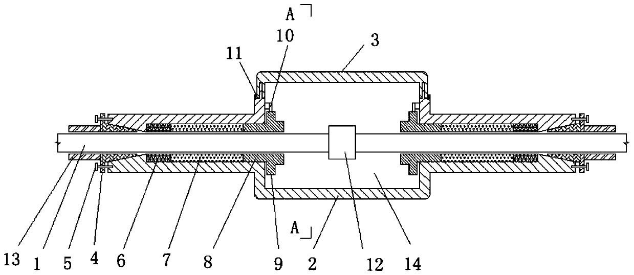
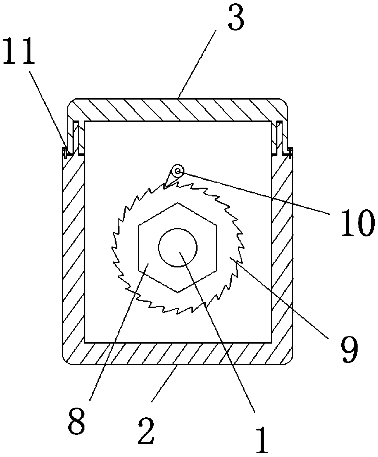
[0047]A floating cable on water includes a cable core, an insulating layer, a waterproof layer, a floating layer, and a floating cable connection device. The floating cable connection device includes a housing 2 and a top cover 3. In this embodiment, a sealing ring is provided between the housing 2 and the top cover 3 and connected by bolts. The casing 2 is integrally formed, and the casing 1 encloses a cable connection chamber 14 and a cable sealing part, and the cable sealing part is arranged on both sides of the cable connection chamber 14 . The cable sealing part is a cylindrical structure and communicates with the cable connection chamber 14 . The end of the cable sealing part away from the cable connection chamber 14 is connected with a tapered sealing block 4, the smaller side of the tapered sealing block 4 faces the cable connecting chamber 14, and the shape of the end of the cable sealing part is also set as a cone. The shape matches the shape of the conical sealing ...

Embodiment 2

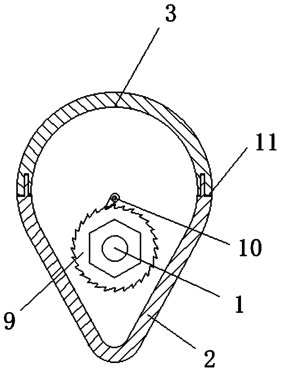
[0057] The technical solution of this embodiment is basically the same as that of Embodiment 1, the difference is that the upper part of the cable connection chamber 14 has an arc-shaped cross-section, the lower part has a V-shaped cross-section, the upper part is a top cover 3, and the lower part is a shell body 2, and the cable sealing part is provided in the lower part of the cable connection chamber 14. This arrangement can make the floating cable connection device float on the water surface, the top cover 3 is always above the water surface, and the top cover 3 is arc-shaped, no water can accumulate on it, and the weight can be reduced.

Embodiment 3

[0059] The technical solution of this embodiment is basically the same as that of Embodiment 1, the difference is that the cross-sectional shape of the cable connection chamber 14 is circular. Such arrangement can make the cable connection chamber 14 have the strongest compressive capacity when the floating cable 1 is in water, and is not easily deformed.


PUM


Abstract

The invention belongs to the technical field of power cables, and particularly relates to a water floating cable. The problems of poor waterproof performance and low tensile strength of the connectionpart of the water floating cable in the prior art are solved. The technical scheme of the invention is as follows: the method comprises the following steps: the cable comprises a cable core, an insulating layer, a waterproof layer and a floating layer and also comprises a floating cable connecting device; the floating cable connecting device comprises a shell and a top cover, the shell is connected with the top cover in a sealed mode; a cable connecting chamber and cable sealing parts arranged on the two sides of the cable connecting chamber are defined by the shell; the cable sealing part isof a cylindrical structure; the end, away from the cable connecting chamber, of the cable sealing part is connected with a conical sealing block, the cable sealing part matches the conical sealing block in shape, and the conical sealing block is connected with the end face of the shell through a fastening bolt. The waterproof performance and the tensile strength of the connection part of the water floating cable are improved, the cable is prevented from being snapped or leaking electricity, and the cable is suitable for supplying power and communicating with mechanical equipment.

Description

technical field [0001] The invention belongs to the technical field of power cables, and in particular relates to a floating cable on water. Background technique [0002] A cable is a tool composed of multiple wires to transmit electrical energy or electrical signals. With the continuous progress of society, the use of electrical energy and electrical signals is becoming more and more common. Cables have become an indispensable part of our lives. In waters such as oceans and rivers, floating cables are needed to provide power and communication for mechanical equipment. Floating cables are important functional elements for the transmission of power and control between equipment such as ships and surface robots and surface or underwater working components. It is related to the function realization and safety guarantee of the ship body and surface or underwater electrical equipment. [0003] In the prior art, the waterproof, tensile strength and other properties of the floatin...

Claims


Application Information

Patent Timeline
IPC IPC(8): H02G15/10H01B7/12
CPCH01B7/12H02G15/10
Inventor 李红东李晓红苟勇朱金
Owner CHENGDU CHUANLAN CABLE
Learn More