Post-collision brake control system and method

A brake control and post-collision technology, which is applied in the directions of automatic starting device, vehicle safety arrangement, pedestrian/passenger safety arrangement, etc., can solve the problems of high development cost, less than 20% of sales volume, and inability to popularize in large quantities, so as to achieve saving The effect of high product cost and popularization rate

Active Publication Date: 2020-03-31
DONGFENG MOTOR CORP HUBEI
View PDF8 Cites 2 Cited by
  • Summary
  • Abstract
  • Description
  • Claims
  • Application Information

AI Technical Summary

Problems solved by technology

[0002] At present, the relevant ICB (post-collision braking) system needs the support of the AEB emergency braking module of the ESC (Electronic Speed ​​Controller, electronic stability control system) in product development and later maintenance; For example, the development and product cost allocation of ESC products supporting Advanced Driving Assistant System (ADAS) is at least 40% higher than that of ESC with basic functions
Although the penetration rate of ADAS systems in intelligent network connection is increasing day by day, according to the authoritative data of China Automobile Consumers Association, the sales volume of vehicles equipped with ADAS functions is less than 7%, and it is expected that the proportion of sales after 2020 will be less than 20%
[0003] The existing post-collision braking uses the ESC to trigger the AEB function to perform partial deceleration and actions. The disadvantage is that it must have hardware and software support, and the equipment rate of AEB is not high and the development cost is high.
leading to the inability to popularize

Method used


Image

  • Post-collision brake control system and method
  • Post-collision brake control system and method

Examples


Embodiment Construction

[0019] Below in conjunction with accompanying drawing and specific embodiment the present invention is described in further detail:

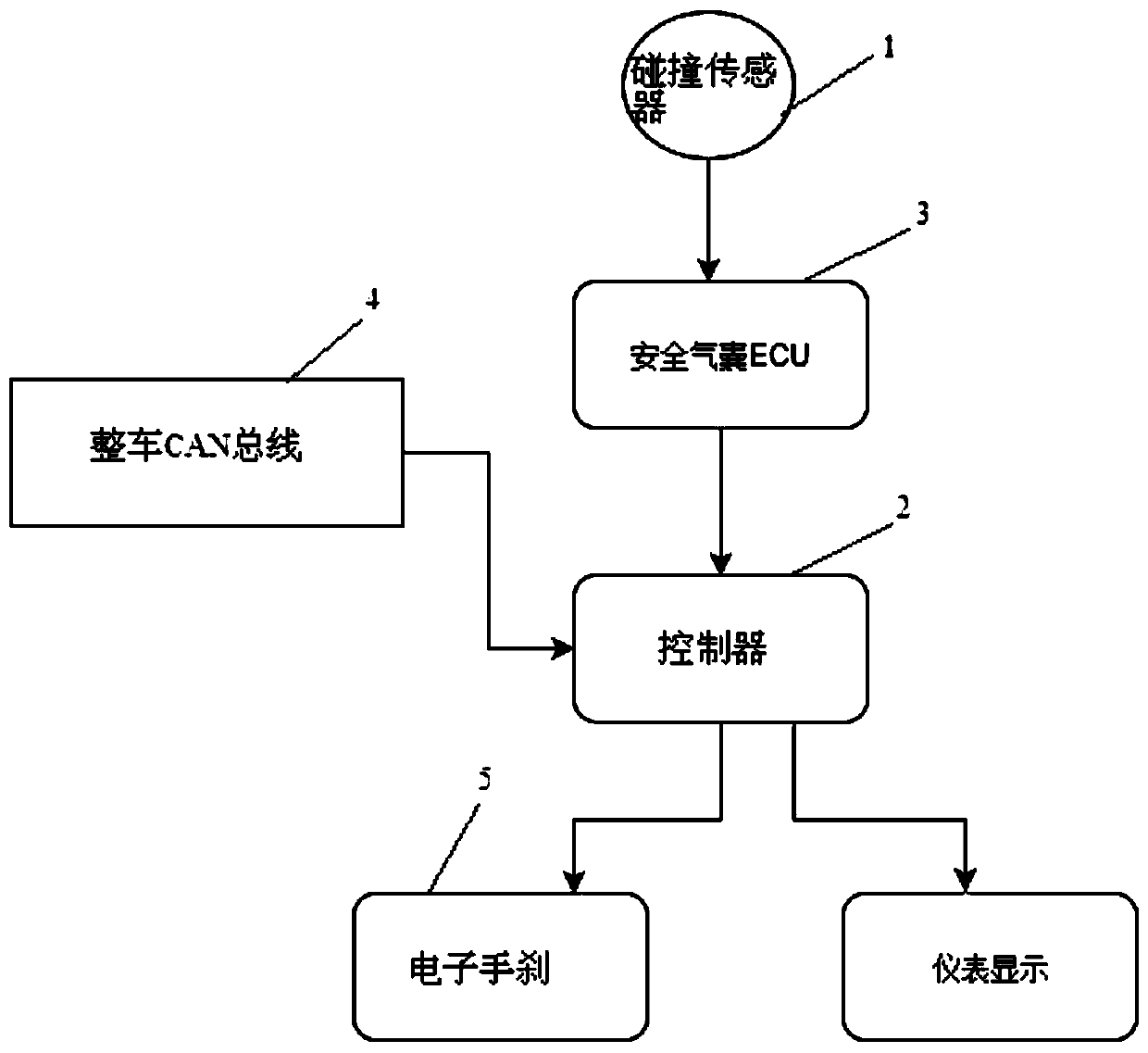
[0020] Such as figure 1 The post-collision braking control system shown includes a collision sensor 1, a controller 2, an airbag ECU 3 and a vehicle CAN bus 4;

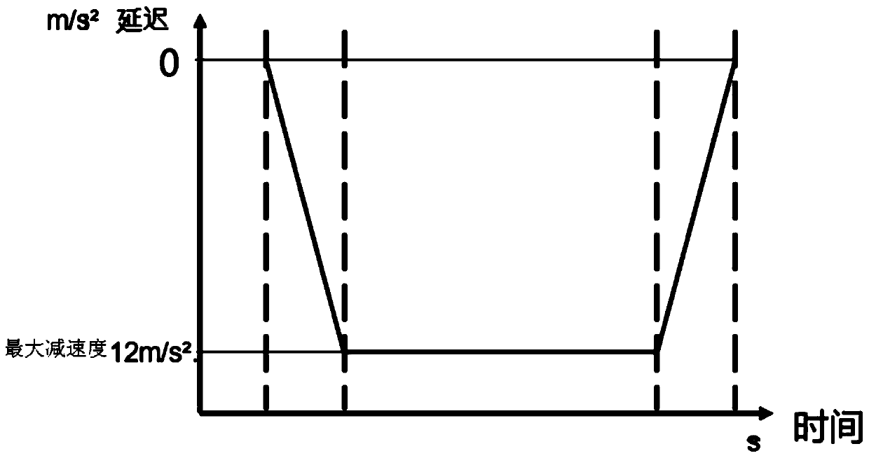
[0021] The controller 2 is used to judge the activation of the braking function after a collision. The controller 2 predicts a MAP map of vehicle speed and braking deceleration. This map draws the most Excellent braking performance and safe tolerable output deceleration curve;

[0022] The vehicle CAN bus 4 is used to provide an ignition switch signal and a real-time vehicle speed signal to the controller 2;

[0023] The collision sensor 1 is used to sense the collision signal, and transmit the collision signal to the airbag ECU3;

[0024] The airbag ECU3 is used to transmit the collision signal to the controller 2. When the braking function is activated after the collision, the cont...


PUM


Abstract

The invention discloses a post-collision brake control system. A controller of the post-collision brake control system judges activation of a post-collision brake function; a whole vehicle CAN bus provides an ignition switch signal and a real-time vehicle speed signal for the controller; the collision sensor senses a collision signal and transmits the collision signal to a safety airbag ECU; the airbag ECU transmits the collision signal to the controller; under the condition that the braking function is activated after collision, the controller triggers the electronic hand brake deceleration function according to the collision signal; and the controller controls the electronic hand brake to decelerate the vehicle according to the vehicle speed, the braking deceleration MAP and the currentvehicle speed until the vehicle speed is reduced to a vehicle speed threshold value for switching between the braking mode and the parking mode, and then the controller continues to control the electronic hand brake to brake in the parking mode. The safety of a driver is improved.

Description

technical field [0001] The invention relates to the technical field of vehicle brake control, in particular to a post-collision brake control system and method. Background technique [0002] At present, the relevant ICB (post-collision braking) system needs the support of the AEB emergency braking module of the ESC (Electronic Speed ​​Controller, electronic stability control system) in product development and later maintenance; For example, the development and product cost allocation of ESC products supporting advanced driving assistance systems (ADAS, Advanced Driving Assistant System) is at least 40% higher than that of ESCs with basic functions. Although the penetration rate of ADAS systems in intelligent network connection is increasing day by day, according to the authoritative data of China Automobile Consumers Association, the sales volume of vehicles equipped with ADAS functions is less than 7%, and it is estimated that the proportion of sales after 2020 will be less...

Claims


Application Information

Patent Timeline
Patent Type & Authority Applications(China)
IPC IPC(8): B60T7/22B60R21/0136
CPCB60R21/0136B60T7/22
Inventor 文翊李泽彬孙国正何班本
Owner DONGFENG MOTOR CORP HUBEI
Why Eureka
Try Eureka