
Quantitative feeder for powdery or micro-granular solids

A technology of tiny particles and powder, applied in the field of quantitative feeder equipment, can solve the problems of difficult quantitative feeding and practical promotion, and achieve the effects of uniform and stable feeding, preventing moisture blockage, and precise control

Active Publication Date: 2020-03-31
陈之中
View PDF6 Cites 2 Cited by
  • Summary
  • Abstract
  • Description
  • Claims
  • Application Information

AI Technical Summary

Problems solved by technology

However, there is a defect in the current condiment feeder, that is, it is difficult to achieve quantitative feeding, especially for solid condiments
[0003] For example, the Intellectual Property Office of the People's Republic of China authorized a patent for invention on November 9, 2005: a method and device for automatically cooking dishes and a method for using condiments, patent No. ZL02102760.9, which discloses a The solid condiment mechanism, the main point of this mechanism is to process all the solid condiments into standard spherical particles first, so as to realize the quantitative processing of them, which obviously greatly increases the threshold of practical promotion, and it is difficult to promote in practice

Method used


Image

  • Quantitative feeder for powdery or micro-granular solids
  • Quantitative feeder for powdery or micro-granular solids
  • Quantitative feeder for powdery or micro-granular solids

Examples


Embodiment Construction

[0021] The application will be described in further detail below in conjunction with the accompanying drawings. It is necessary to point out that the following specific embodiments are only used to further illustrate the application, and cannot be interpreted as limiting the protection scope of the application. The above application content makes some non-essential improvements and adjustments to this application.

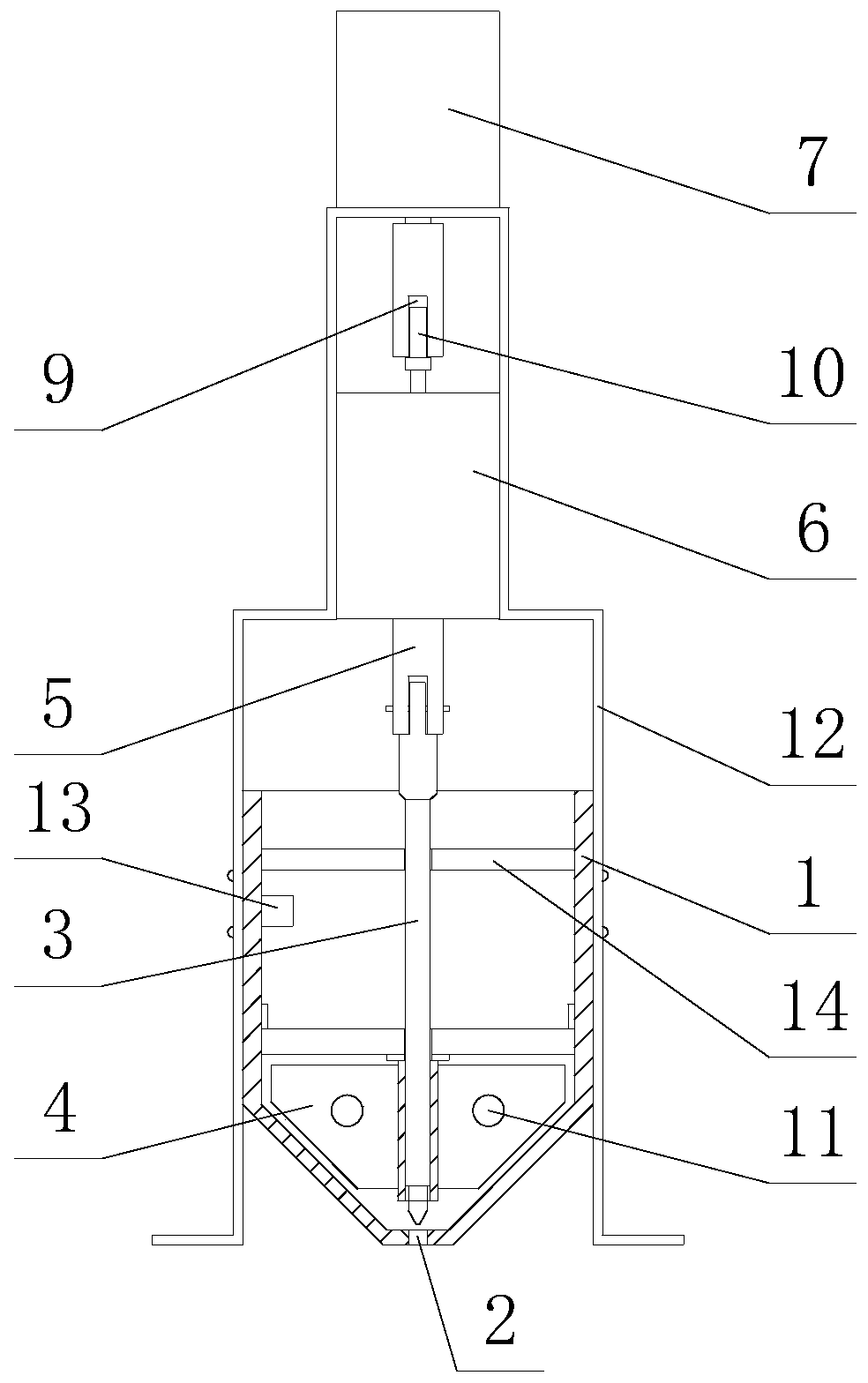
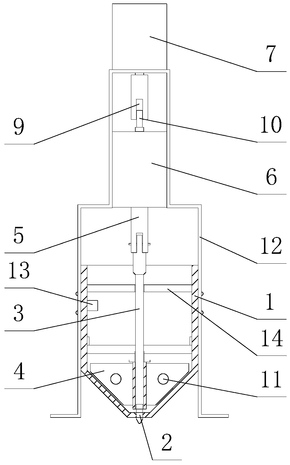
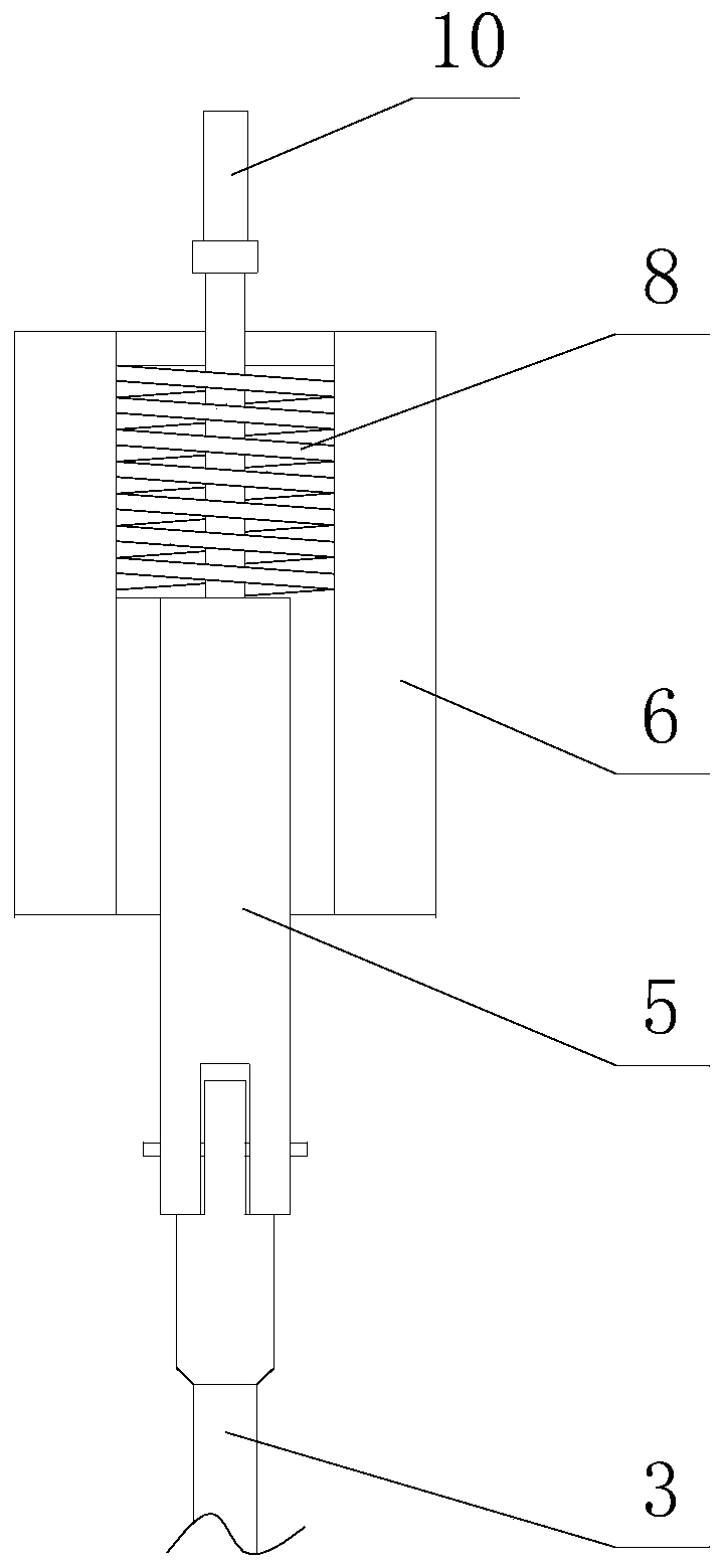
[0022] Combine graph to image 3 As shown, a quantitative feeder for powdery or tiny granular solids includes a raw material container 1, the bottom of the raw material container 1 is provided with a discharge hole 2, and the axis of the raw material container 1 is provided with a rotating shaft 3, the rotating shaft The bottom of 3 is connected with stirring plate 4, and the top of rotating shaft 3 is provided with electromagnet 6, and the top of described rotating shaft 3 is coaxially fixedly connected with the iron mandrel 5 protruding from the bottom of this el...


PUM


Abstract

The invention discloses a quantitative feeder for powdery or micro-granular solids. The feeder comprises a raw material container, wherein discharging holes are formed in the lowest end of the raw material container, a rotating shaft is arranged at the axial line of the raw material container, a stirring blade is connected at the lower part of the rotating shaft, an electromagnet is arranged at the upper part of the rotating shaft, the top of the rotating shaft is fixedly connected with an iron core rod extending from the lower part of the electromagnet, the electromagnet is connected with a power supply, a motor is arranged above the electromagnet, the protruding part at the top of the iron core rod is movably connected with an output shaft of the motor, and the iron core rod drives the rotating shaft to move up and down under the magnetic force action of the electromagnet. The feeder can realize the control over the feeding quantity of raw materials only by controlling the power to be on and off and can keep the raw materials in a loose state all the time due to the introduction of the stirring effect, the discharging is uniform and stable, and the situations of caking and material blocking cannot occur; and meanwhile, the phenomenon of blocking, caused by moisture, of the discharging holes can also be prevented, in this way, the adding quantity of the raw materials can be controlled by controlling the length of the adding time, and by means of the mode, the control is more accurate and convenient, and the practical popularization is facilitated.

Description

technical field [0001] The invention relates to the field of quantitative feeder equipment, in particular to a quantitative feeder for powdery or tiny granular solids. Background technique [0002] Quantitative feeders are widely used in various fields, especially when cooking dishes, a certain amount of condiments need to be added accurately to improve their color and taste, so as to meet the needs of diverse groups of people. Correspondingly, some automatic dish cooking equipments are also equipped with auxiliary feeders for adding condiments. However, there is a defect in the current condiment feeder, that is, it is difficult to realize quantitative feeding, especially for solid condiments. [0003] For example, the Intellectual Property Office of the People's Republic of China authorized a patent for invention on November 9, 2005: a method and device for automatically cooking dishes and a method for using condiments, patent No. ZL02102760.9, which discloses a The solid...

Claims


Application Information

Patent Timeline
Patent Type & Authority Applications(China)
IPC IPC(8): B65G65/40B01F7/18
CPCB65G65/40B01F27/90
Inventor 陈之中陈仰帆
Owner 陈之中
Learn More